
Dual-band Broadband Patch Circularly Polarized Antenna

A circularly polarized antenna and patch technology, applied in the field of satellite communications, can solve problems such as unfavorable work, unfavorable radio frequency front-end integration of circularly polarized antennas, bulky feeding network, etc., to achieve broadband characteristics and excellent circularly polarized performance. , to achieve the effect of miniaturization

Inactive Publication Date: 2020-02-04
X TRIP INFORMATION TECH CO LTD
View PDF6 Cites 0 Cited by
  • Summary
  • Abstract
  • Description
  • Claims
  • Application Information

AI Technical Summary

Problems solved by technology

[0003] The main purpose of the present invention is to provide a dual-frequency broadband patch circularly polarized antenna, which aims to solve the problem that the existing feeding network is bulky, which is not conducive to the integration of the radio frequency front end of the circularly polarized antenna, and most of them work at a single frequency point, which is not easy to solve. Technical Issues Facilitating Operation in Multi-Frequency or Broadband Conditions

Method used


Image

  • Dual-band Broadband Patch Circularly Polarized Antenna
  • Dual-band Broadband Patch Circularly Polarized Antenna
  • Dual-band Broadband Patch Circularly Polarized Antenna

Examples


Embodiment Construction

[0024] In order to further illustrate the technical means and effects of the present invention to achieve the above objectives, the specific implementation, structure, features and effects of the present invention will be described in detail below in conjunction with the accompanying drawings and preferred embodiments. It should be understood that the specific embodiments described here are only used to explain the present invention, not to limit the present invention.

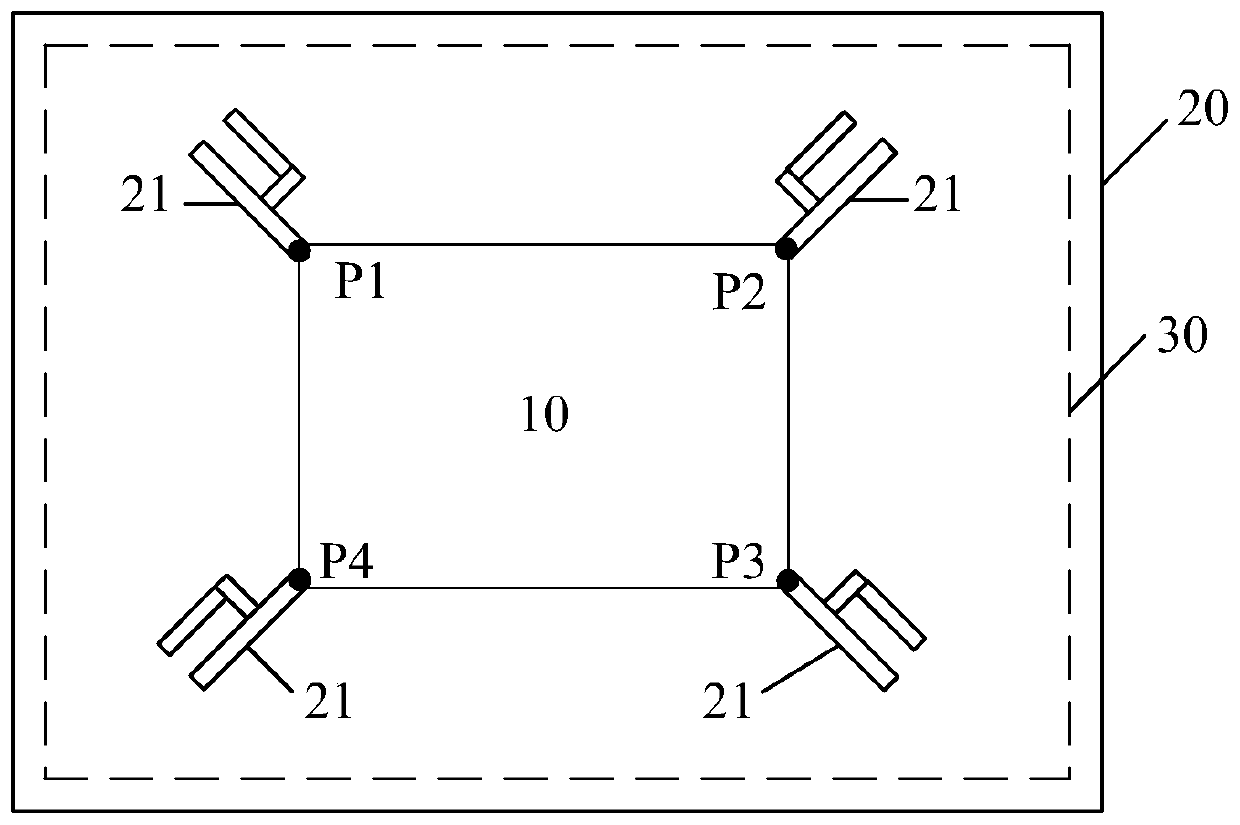
[0025] refer to figure 1 as shown, figure 1 It is a schematic plan view of a preferred embodiment of the dual-band broadband patch circularly polarized antenna of the present invention. In this embodiment, the dual-band broadband patch circularly polarized antenna includes a feed network 10 , a dielectric board 20 and a copper-clad metal ground 30 , and the feed network 10 is integrated on the dielectric board 20 . The dielectric board 20 is provided with four dual-frequency monopole radiation patches 21, an...


PUM


Abstract

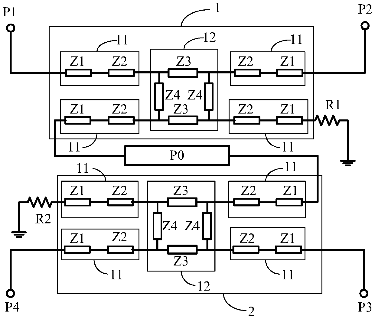
The invention discloses a dual-frequency broadband patch circularly polarized antenna, which includes a dielectric plate and a copper-clad metal ground. Four dual-frequency monopole radiation patches and a feeding network are arranged on the dielectric plate. The four dual-frequency monopoles are The radiation patch is connected to the four ports of the feed network in turn. The feed network includes a coaxial connector, a first dual-frequency coupler and a second dual-frequency coupler. The signal line of the coaxial connector is connected to the first dual-frequency coupler. The input end of the coaxial connector is connected to the input end of the second dual-band coupler. The through end of the first dual frequency coupler is connected to the first port, the coupling end of the first dual frequency coupler is connected to the second port, the isolation end of the first dual frequency coupler is connected to the first resistor; the through end of the second dual frequency coupler is connected to the first port. The terminal is connected to the fourth port, the coupling terminal of the second dual-frequency coupler is connected to the third port, and the isolation terminal of the second dual-frequency coupler is connected to the second resistor. The present invention realizes the miniaturization, dual-frequency characteristics or broadband characteristics of the circularly polarized antenna through the reasonable layout of the feed network.

Description

technical field [0001] The invention relates to the technical field of satellite communication, in particular to a dual-frequency broadband patch circularly polarized antenna. Background technique [0002] In recent years, with the rapid development and wide application of satellite navigation and satellite communications, circularly polarized antennas are used as front-end equipment for these systems, and their performance indicators play an important role in the performance of satellite communications handheld terminals and RFID card reading devices extremely important role. In addition, in order to facilitate the large-scale popularization and application of satellite communication terminals and radio frequency identification systems, the economic cost and volume of the system are crucial considerations. Under the premise, it must have the characteristics of low cost, compact structure and small size. When feeding circularly polarized antennas or array antennas, it is n...

Claims


Application Information

Patent Timeline
Patent Type & Authority Patents(China)
IPC IPC(8): H01Q1/50H01Q15/24H01Q5/50
CPCH01Q1/50H01Q5/50H01Q15/24
Inventor 曲美君邓力李书芳张贯京葛新科高伟明张红治
Owner X TRIP INFORMATION TECH CO LTD
Learn More