RFID circularly polarized air microstrip antenna

A microstrip antenna, circularly polarized technology, applied in the direction of the antenna, antenna grounding switch structure connection, electrical components, etc., can solve the problems of high cost of dielectric materials, narrow bandwidth, large loss, etc., to achieve wide impedance and axial ratio bandwidth, The effect of improving circular polarization performance and highlighting substantive features

Pending Publication Date: 2020-05-15
SHANDONG GUANTONG INTELLIGENT TECH CO LTD
View PDF11 Cites 4 Cited by
  • Summary
  • Abstract
  • Description
  • Claims
  • Application Information

AI Technical Summary

Problems solved by technology

Among them, due to the high cost of dielectric materials, large loss, and narrow bandwidth, the application scenarios of dielectric interlayer microstrip patch antennas are limited.
The (type) even / monopole antenna array, due to its high profile, large volume and complex structure, cannot be well adapted to the application of narrow spaces.

Method used


Image

  • RFID circularly polarized air microstrip antenna
  • RFID circularly polarized air microstrip antenna
  • RFID circularly polarized air microstrip antenna

Examples


Embodiment Construction

[0031] Specific embodiments of the present invention will be described below in conjunction with the accompanying drawings.

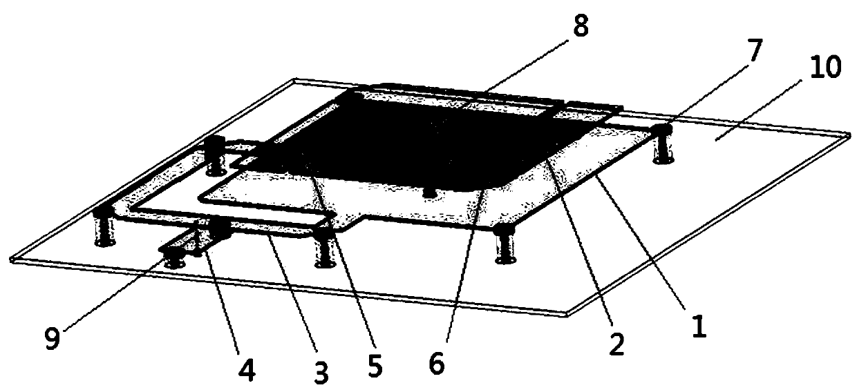
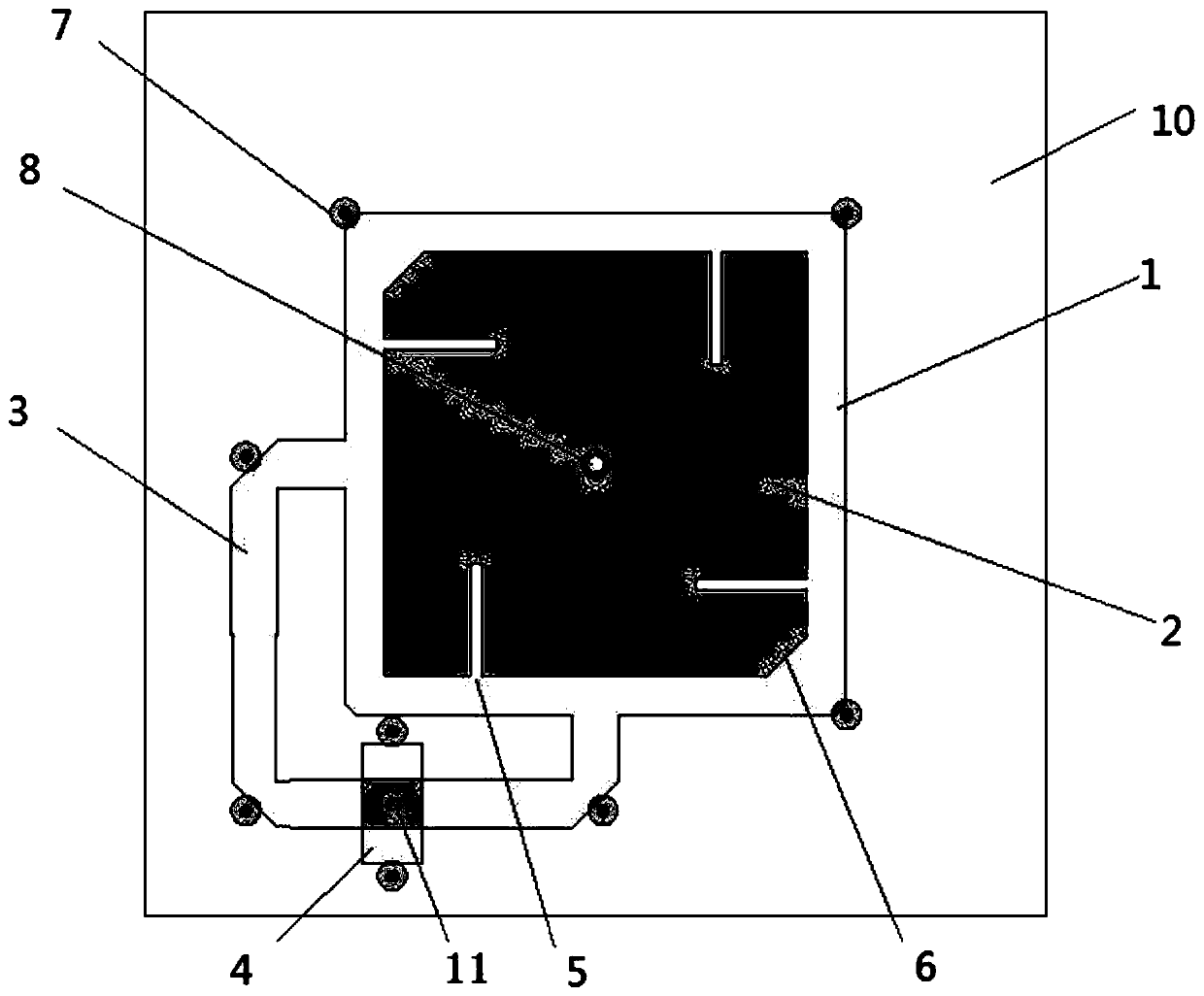
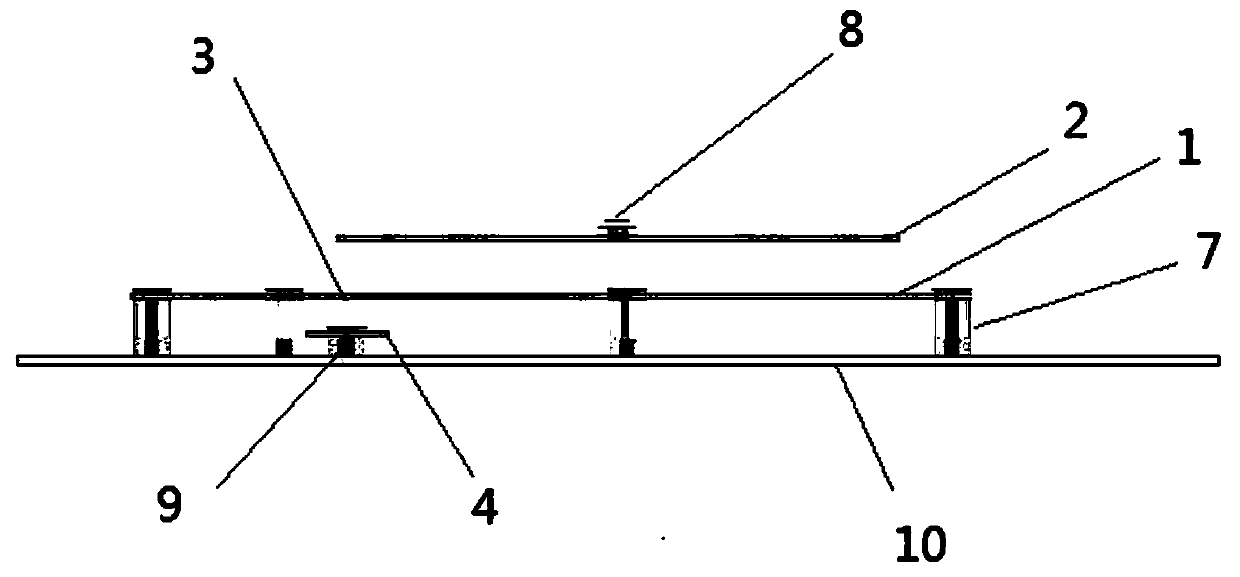
[0032] like Figure 1-3 In the shown RFID circularly polarized air microstrip antenna, the bottom part is a square metal grounding plate 10, and the metal tuning plate 4, the lower metal radiation patch 1 and the center position of its side length are arranged in sequence above the metal grounding plate 10. The connected feed network 3 and the upper metal radiation patch 2. Wherein, the upper metal radiation patch 2 is rectangular, a group of diagonal corners of the upper metal radiation patch 2 are cut corners 6 , and each side of the upper metal radiation patch 2 is provided with a rectangular slot 5 extending inward. The feeding probe 9 is connected to the center of the bottom of the metal tuning piece 4, and the metal tuning piece 4 is welded to the bottom of the feeding network 3 through metal screws. Both the lower radiating metal patch 1 and th...


PUM


Abstract

An RFID circularly polarized air microstrip antenna provided by the invention is characterized in that a lower-layer metal radiation patch is arranged above a metal grounding plate, and an upper-layermetal radiation patch is arranged above the lower-layer metal radiation patch; a metal pillar is fixedly installed in the center of the metal grounding plate, and the upper metal radiation patch andthe lower metal radiation patch are fixedly installed on the metal pillar through the installation holes respectively; a feed network is L-shaped and is connected with the lower radiation patch, a metal tuning sheet is arranged between the feed network and the metal grounding plate, a metal screw is arranged between the metal tuning sheet and the feed network, and a feed probe is welded at the bottom of the metal tuning sheet. The antenna has the advantages of being small in size, low in profile, large in gain, wider in 3dB axial ratio and impedance bandwidth and the like, the impedance bandwidth of the antenna can be increased, the standing-wave ratio of the antenna can be reduced, the axial ratio of the antenna can be effectively reduced, and the ideal axial ratio bandwidth can be obtained.

Description

technical field [0001] The invention relates to the technical field of antennas, in particular to an RFID circularly polarized air microstrip antenna. Background technique [0002] Radio frequency identification technology (Radio Frequency Identification, RFID) is a kind of automatic identification technology. It performs non-contact two-way data communication through radio frequency, and uses radio frequency to read and write recording media (electronic tags or radio frequency cards), so that To achieve the purpose of identifying targets and data exchange. In the RFID communication system, external hardware devices can be divided into host computer systems (including databases and data processing programs), RFID readers, RFID near / far field antennas, and electronic tags. The ring plays a key role in the stability and recognizability of the signal. [0003] At present, RFID far-field high-gain antennas generally adopt the form of dielectric interlayer microstrip patch ante...

Claims


Application Information

Patent Timeline
IPC IPC(8): H01Q1/36H01Q1/38H01Q1/50H01Q13/08
CPCH01Q1/36H01Q1/38H01Q1/50H01Q13/08
Inventor 徐长吉胡天威颜勃
Owner SHANDONG GUANTONG INTELLIGENT TECH CO LTD
Why Eureka
Try Eureka