Eight-arm spiral circularly-polarized dual-band antenna applicable to laser direct forming technology

A laser direct forming, dual-frequency antenna technology, which is applied to the structural connection of the antenna, the antenna grounding switch, and the device that enables the antenna to work in different frequency bands at the same time. and other problems, to achieve the effect of being conducive to mass production, low elevation gain, and easy production and processing

Pending Publication Date: 2018-05-29
THE FIRST RES INST OF TELECOMMTECH
View PDF0 Cites 2 Cited by
  • Summary
  • Abstract
  • Description
  • Claims
  • Application Information

AI Technical Summary

Problems solved by technology

For narrow-bandwidth antennas, the dimensional tolerance control of the above process is relatively poor, which can easily cause impedance mismatch and frequency drift, resulting in product quality degradation or low yield
[0003] There are also some spiral antennas that are realized by printing silver paste. Due to the complicated printing process, the silver paste needs to be dried after printing to print the other side. Most of them are only for flat or simple curved surface products, and the pattern connection between the surface and the surface It is difficult to control the accuracy
The more common printed ceramic antennas, although miniaturized, have narrower bandwidths and are mostly only suitable for receiving antennas

Method used


Image

  • Eight-arm spiral circularly-polarized dual-band antenna applicable to laser direct forming technology
  • Eight-arm spiral circularly-polarized dual-band antenna applicable to laser direct forming technology
  • Eight-arm spiral circularly-polarized dual-band antenna applicable to laser direct forming technology

Examples


Embodiment Construction

[0044] The specific embodiments of the present invention are given below in conjunction with the accompanying drawings, but the present invention is not limited to the following embodiments. Advantages and features of the present invention will be apparent from the following description and claims. It should be noted that all the drawings are in very simplified form and use imprecise ratios, which are only used for the purpose of conveniently and clearly assisting in describing the embodiments of the present invention.

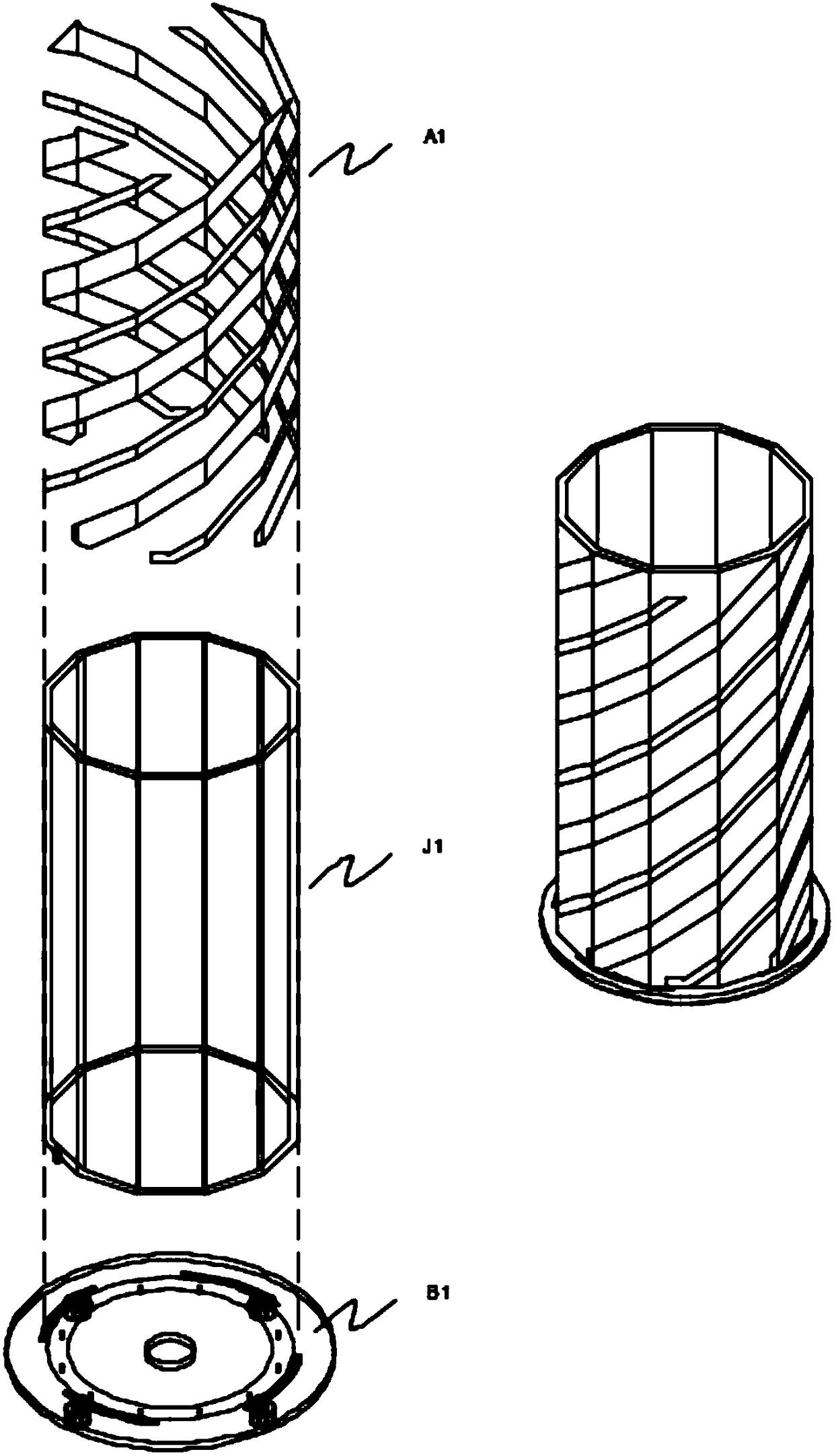
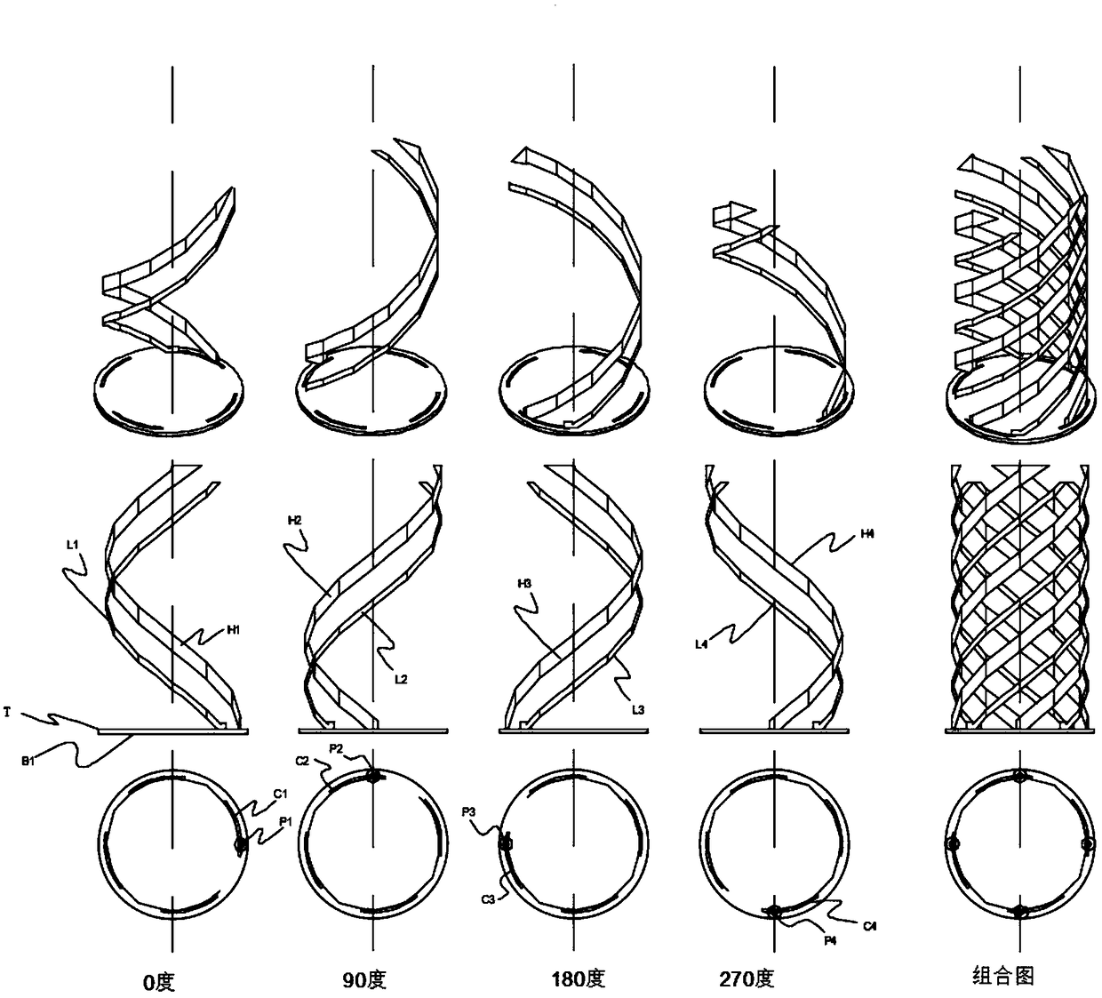
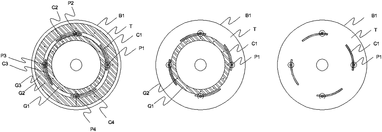
[0045] Please refer to figure 1 with figure 2 , the present invention proposes an eight-arm helical circularly polarized dual-frequency antenna suitable for laser direct forming technology, including: antenna dielectric body J1; antenna resonator A1, which is arranged in cooperation with the antenna dielectric body J1 to form an integral antenna; antenna The circuit board B1 is connected and arranged at the bottom of the antenna dielectric body J1 and the a...


PUM


Abstract

The invention provides an eight-arm spiral circularly-polarized dual-band antenna applicable to a laser direct forming technology. The eight-arm spiral circularly-polarized dual-band antenna comprisesan antenna dielectric body, an antenna resonance body which is matched with the antenna dielectric body, and an antenna circuit board which is connected with and arranged at the bottoms of the antenna dielectric body and the antenna resonance body, wherein the antenna dielectric body is a 12-prism object, wherein the side surfaces of the antenna dielectric body consist of 12 equivalent faces; theantenna resonance body is arranged on the antenna dielectric body; the antenna resonance body is arranged around the antenna dielectric body; the antenna resonance body comprises four high-frequencyspiral arms, including a first high-frequency spiral arm, a second high-frequency spiral arm, a third high-frequency spiral arm and a fourth high-frequency spiral arm, and four low-frequency spiral arms, including a first low-frequency spiral arm, a second low-frequency spiral arm, a third low-frequency spiral arm and a fourth low-frequency spiral arm in four groups; each group comprises a high-frequency spiral arm and a low-frequency spiral arm; and the antenna resonance body consists of a conductive body. The eight-arm spiral circularly-polarized dual-band antenna is wide in frequency band,can be produced and manufactured easily, low in elevation and high in gain, and suitable for satellite both-way communication.

Description

technical field [0001] The invention relates to the field of microwave technology and antennas, and in particular to an eight-arm helical circularly polarized dual-frequency antenna suitable for laser direct forming technology. Background technique [0002] Existing four-arm helical antennas are divided into short-circuit type and open-circuit type. All have the characteristics of wide beam circular polarization and high gain at low elevation angles. The beam of the short-circuit type is wider than that of the open-circuit type, and the gain in one direction is not as high as that of the open-circuit type. But there are shortcomings of narrow frequency bandwidth. In terms of technology, most of the four-arm helical antennas are realized by wrapping a cylinder with a flexible circuit board or winding a copper wire. For narrow-bandwidth antennas, the dimensional tolerance control of the above process is relatively poor, which can easily cause impedance mismatch and frequenc...

Claims


Application Information

Patent Timeline
IPC IPC(8): H01Q1/38H01Q1/50H01Q5/10H01Q5/307
CPCH01Q1/38H01Q1/50H01Q5/10H01Q5/307
Inventor 史纪元
Owner THE FIRST RES INST OF TELECOMMTECH
Why Eureka
Try Eureka