
A Method of Improving Alarm Reliability of Distributed Optical Fiber Monitoring System

A distributed optical fiber and monitoring system technology, applied to alarms, instruments, etc., can solve the problems that the system cannot set alarm thresholds, different values, etc.

Active Publication Date: 2020-08-14
BEIJING INST OF AEROSPACE CONTROL DEVICES
View PDF7 Cites 0 Cited by
  • Summary
  • Abstract
  • Description
  • Claims
  • Application Information

AI Technical Summary

Problems solved by technology

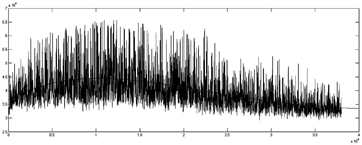
[0004] The existing distributed optical fiber monitoring systems of the same kind are all demodulated by demodulating the collected backscattered light signal. Since the optical power distribution of the system is different on the entire sensing fiber, it will cause different positions of the sensing fiber. The "sensitivity" of environmental information perception such as vibration and temperature is different. The disadvantage of this method is that the system cannot set appropriate Alarm threshold, effective early warning of environmental disturbance information such as vibration and temperature that may cause harm

Method used


Image

  • A Method of Improving Alarm Reliability of Distributed Optical Fiber Monitoring System
  • A Method of Improving Alarm Reliability of Distributed Optical Fiber Monitoring System
  • A Method of Improving Alarm Reliability of Distributed Optical Fiber Monitoring System

Examples


Embodiment Construction

[0029] The present invention will be described in detail below in conjunction with the accompanying drawings and examples.

[0030] like figure 1 As shown, a method for improving the reliability of the alarm of the distributed optical fiber monitoring system of the present invention, the specific steps are as follows:

[0031] During the operation of the distributed optical fiber sensing system, the backscattered light interference signal (hereinafter referred to as real-time signal data) is collected in real time. Set a set of real-time signal data to be selected every 50ms;

[0032] Use the Hilbert transform to process the selected real-time signal data, and convert the original signal into a complex analysis signal. The Hilbert transform formula is as follows:

[0033]

[0034] Among them, x(t) is a group of selected real-time signal data, x. The original signal data is converted into complex analytical signal data through Hilbert transform, and then the complex analy...


PUM


Abstract

The invention relates to a method for improving the alarm reliability of a distributed optical fiber monitoring system. During the operation process of a distributed optical fiber monitoring system, one group of real-time backscattering optical signal data are selected regularly; upper enveloping curve data of the group of real-time backscattering optical signal data are calculated; polynomial curve fitting processing is carried out on the upper enveloping curve data and an upper enveloping curve function expression is obtained; according to the upper enveloping curve function expression, a calibration coefficient corresponding to each point of the monitoring processing effect curve is calculated according to the upper enveloping curve function expression, wherein the horizontal coordinateof the monitoring processing effect curve represents a corresponding physical position of the sensing fiber for monitoring and the vertical coordinate represents a physical quantity intensity monitored by the system; according to the calibration coefficients, the monitoring processing effect curve is calibrated; and during the operation process of the distributed optical fiber monitoring system,vertical coordinate values of all points on the monitoring processing effect curve after calibration are compared with an alarm threshold regularly, and warning is carried out when the vertical coordinate values exceed an alarm threshold value.

Description

technical field [0001] The invention belongs to the technical field of distributed optical fiber sensing. Background technique [0002] The distributed optical fiber sensing system can sense and locate information such as vibration and temperature at any point on the sensing fiber, and is widely used in perimeter security, oil and gas pipeline leakage, power cables, communication line monitoring, and structural safety monitoring. [0003] The distributed optical fiber monitoring system involved in the present invention is based on the OTDR principle. Changes in the vibration and temperature environment along the sensing optical fiber will cause changes in the refractive index of the optical fiber at the corresponding position, and the phase of the backscattered light there will also change accordingly. By measuring the change The time when the light intensity returns can calculate its position information. By collecting and demodulating the backscattered light signal, the sy...

Claims


Application Information

Patent Timeline
Patent Type & Authority Patents(China)
IPC IPC(8): G08B29/18
CPCG08B29/185
Inventor 李成志梁同利刘诚王学锋王明超郑春雷宋海滨
Owner BEIJING INST OF AEROSPACE CONTROL DEVICES
Learn More