
Humidifier with double-valve structure

A humidifier and valve body technology, which is applied in the field of the valve structure of the humidifier water tank, can solve the problems of causing danger, leaking to the outside of the humidifier, water leakage of the humidifier water tank, etc., so as to achieve improved reliability, high safety factor and optimized performance. Effect

Active Publication Date: 2018-07-06
FOSHAN JINXINGHUI ELECTRICAL APPLIANCE
View PDF11 Cites 10 Cited by
  • Summary
  • Abstract
  • Description
  • Claims
  • Application Information

AI Technical Summary

Problems solved by technology

The technical solution provided by this utility model has the following disadvantages: when the water sealing member, spring or pressure rod cannot work normally, the water outlet of the humidifier water tank will not be closed normally, which will easily cause the water in the humidifier water tank to leak completely. Flood the electrical components of the humidifier or leak out of the humidifier, causing danger

Method used


Image

  • Humidifier with double-valve structure
  • Humidifier with double-valve structure
  • Humidifier with double-valve structure

Examples


Embodiment 1

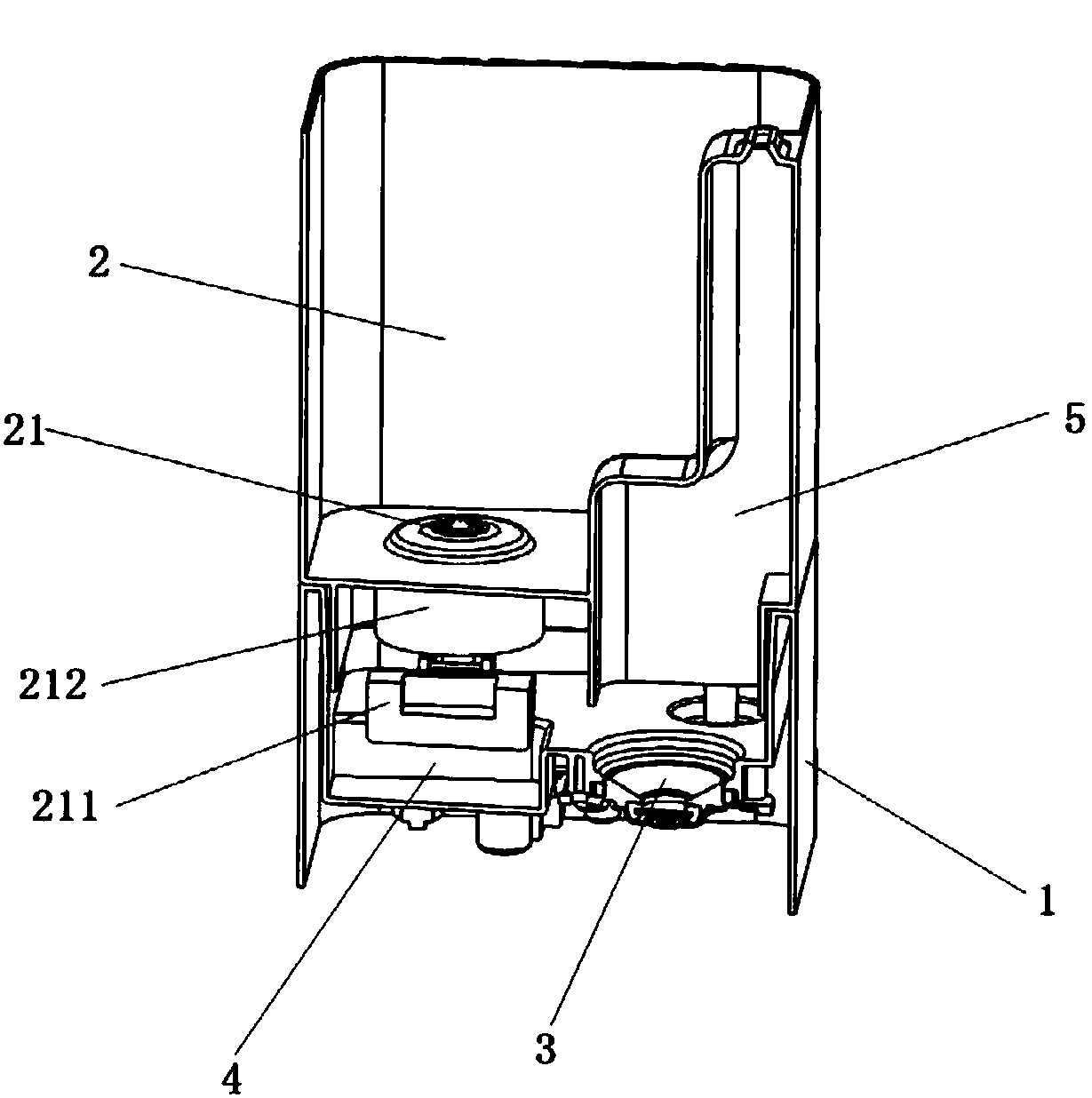
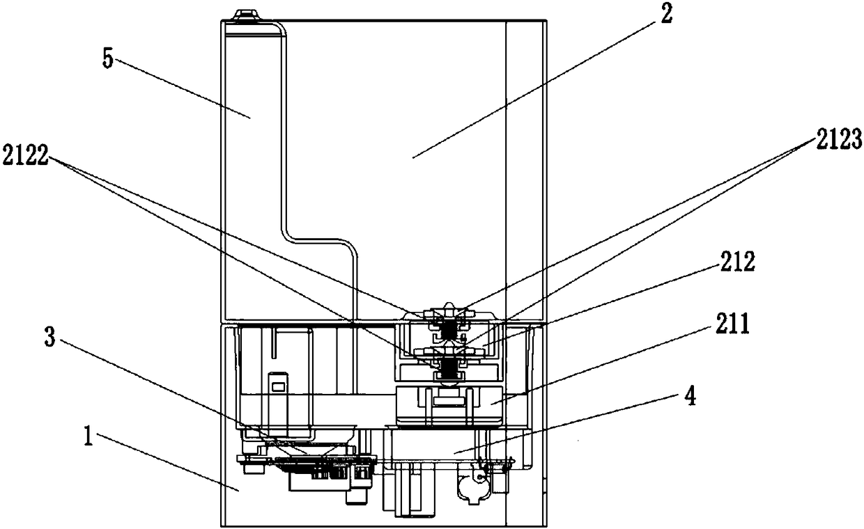
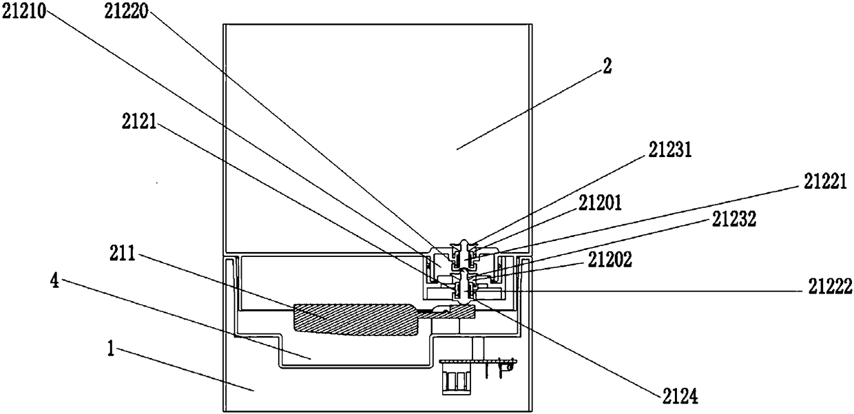
[0033] see Figure 1 to Figure 6 As shown, a humidifier with a double-valve structure includes a base 1, a water tank 2, an atomizing device 3, a water storage chamber 4, and a mist outlet channel 5. The base 1 is provided with a water storage chamber 4, and the water storage chamber 4 An atomizing device 3 is provided, and the mist generated by the atomizing device 3 is discharged out of the humidifier through the mist outlet channel 5. The water tank 2 has a drain port 21, and the drain port 21 has a drain control device, which includes a detection and driving mechanism 211 and a drain unit 212, the water outlet 212 is arranged at the water outlet 21, the water outlet 212 has the first water outlet hole 21201 and the second water outlet hole 21202 connected in series, the first water outlet hole 21201 and the second water outlet hole 21202 are respectively provided with a valve body, the valve The body acts according to the signal generated by the detection and driving mecha...

Embodiment 2

[0045] Except as follows, the structure described in this embodiment is the same as in Example 1:

[0046] see Figure 4 As shown, the linkage mechanism 21220 is a soft link set on the top of the second valve core 21222, the soft link is inserted into the bottom of the first valve core 21221, the first water sealing part 21231 is located below the first water outlet hole 21201, and the second sealing The water element 21232 is located below the second water outlet hole 21202 . Preferably, the first water sealing member 21231 is fixedly connected to the top of the first valve core 21221, and the second water sealing member 21232 is fixedly connected to the top of the second valve core 21222.

[0047] In the above technical solution provided by the invention, when the detection and driving mechanism generates a water shortage signal, the float located in the reservoir moves downward and drives the lever connected to it to move around the axis, and the side of the lever connecte...

Embodiment 3

[0049] Except as follows, the structure described in this embodiment is the same as in Example 1:

[0050] see Figure 5 As shown, the linkage mechanism 21220 includes an inclined-plane body arranged on the second valve core 21222 and an inclined-plane chute arranged on the first valve core 21221. The inclined-plane body is inserted into the inclined-plane chute and can drive the first valve core to move forward 21221 , the first valve core 21221 and the second valve core 21222 are arranged at an angle. Preferably, the first valve core 21221 is set in a horizontal direction, and the second valve core 21222 is set in a vertical direction, that is, the first valve core 21221 and the second valve core 21222 are set at 90°. Preferably, the first water sealing member 21231 is located in front of the first water outlet hole 21201 , and the second water sealing member 21232 is located above the second water outlet hole 21202 . Preferably, the first water sealing member 21231 is fix...


PUM


Abstract

A humidifier with a double-valve structure comprises a base, a water tank, an atomization device, a water accumulation chamber and a mist outlet channel. The water accumulation chamber is arranged onthe base and provided with the atomization device. Mist generated by the atomization device is discharged out of the humidifier through the mist outlet channel. A water discharging port is formed in the water tank and provided with a water discharging control device. The water discharging control device comprises a detection and drive mechanism and a water discharging part. The water discharging part is arranged at the position of the water discharging port. The water discharging part is provided with a first water outlet hole and a second water outlet hole which are connected in series. The first water outlet hole and the second water outlet hole are provided with valves correspondingly, the valves act according to signals generated by the detection and drive mechanism and open or close the first water outlet hole and the second water outlet hole, and the valves independently close the first water outlet hole and the second water outlet hole. Compared with the prior art, the providedhumidifier with the water discharging part structure has the following beneficial effects that the water leakage probability is reduced, security is high, the safety coefficient is high, and performance is better optimized.

Description

technical field [0001] The invention relates to the field of humidifier water tank valve structures, in particular to a humidifier with a double valve body structure. Background technique [0002] Humidifiers currently on the market generally use a single-valve structure to control the water outlet of the humidifier water tank. When the water level in the water tank or atomization tank / vaporization tank is too low, a water shortage signal is sent to the valve, prompting the valve to open, and the humidifier tank The water in the tank enters the tank or the atomization tank / vaporization tank; when the water level in the tank or the atomization tank / vaporization tank rises to a predetermined value, the water stop signal is sent to the valve, which prompts the valve to close, and the water in the humidifier tank stops flowing in Sink or mist / vapor tank. However, the single valve structure of the above-mentioned water tank cannot overcome the water tank leakage problem caused w...

Claims


Application Information

Patent Timeline
Patent Type & Authority Applications(China)
IPC IPC(8): F24F6/12F24F6/00
CPCF24F6/00F24F6/12F24F2006/008Y02B30/70
Inventor 蔡镜波杨雄
Owner FOSHAN JINXINGHUI ELECTRICAL APPLIANCE
Learn More