
Foundation pit underground water recharge system

A groundwater and foundation pit technology, which is applied in multi-stage water treatment, water/sewage treatment, infrastructure engineering, etc., can solve problems such as foundation soil consolidation, endangering public safety, and increase in effective self-weight stress of the soil, achieving treatment Good effect, high treatment effect, water quality guarantee effect

Active Publication Date: 2018-07-06
温州华睿建设有限公司
View PDF7 Cites 3 Cited by
  • Summary
  • Abstract
  • Description
  • Claims
  • Application Information

AI Technical Summary

Problems solved by technology

[0002] In foundation pit engineering, in order to ensure that the earth excavation and foundation construction are in a dry state or to improve the stability of the foundation pit slope, the precipitation method is often used to reduce the groundwater in or outside the foundation pit to below the excavation surface, but with the groundwater As the water level decreases, the effective self-gravity stress of the soil below the original water level in the foundation increases, resulting in the consolidation of the foundation soil, which in turn causes uneven settlement, inclination, and cracking of the ground and buildings within the area affected by precipitation, which may endanger its safe and normal use
[0003] In order to eliminate the impact of foundation pit precipitation on the surrounding environment, the recharge method is usually used to eliminate the impact of foundation pit precipitation on the surrounding environment, but during recharge, the water quality of the recharge into the ground cannot be guaranteed, resulting in the impact of groundwater quality , seriously endangering public safety

Method used


Image

  • Foundation pit underground water recharge system
  • Foundation pit underground water recharge system
  • Foundation pit underground water recharge system

Examples


Embodiment Construction

[0033] The present invention will be described in further detail below in conjunction with the accompanying drawings.

[0034] This specific embodiment is only an explanation of the present invention, and it is not a limitation of the present invention. Those skilled in the art can make modifications to this embodiment without creative contribution as required after reading this specification, but as long as they are within the rights of the present invention All claims are protected by patent law.

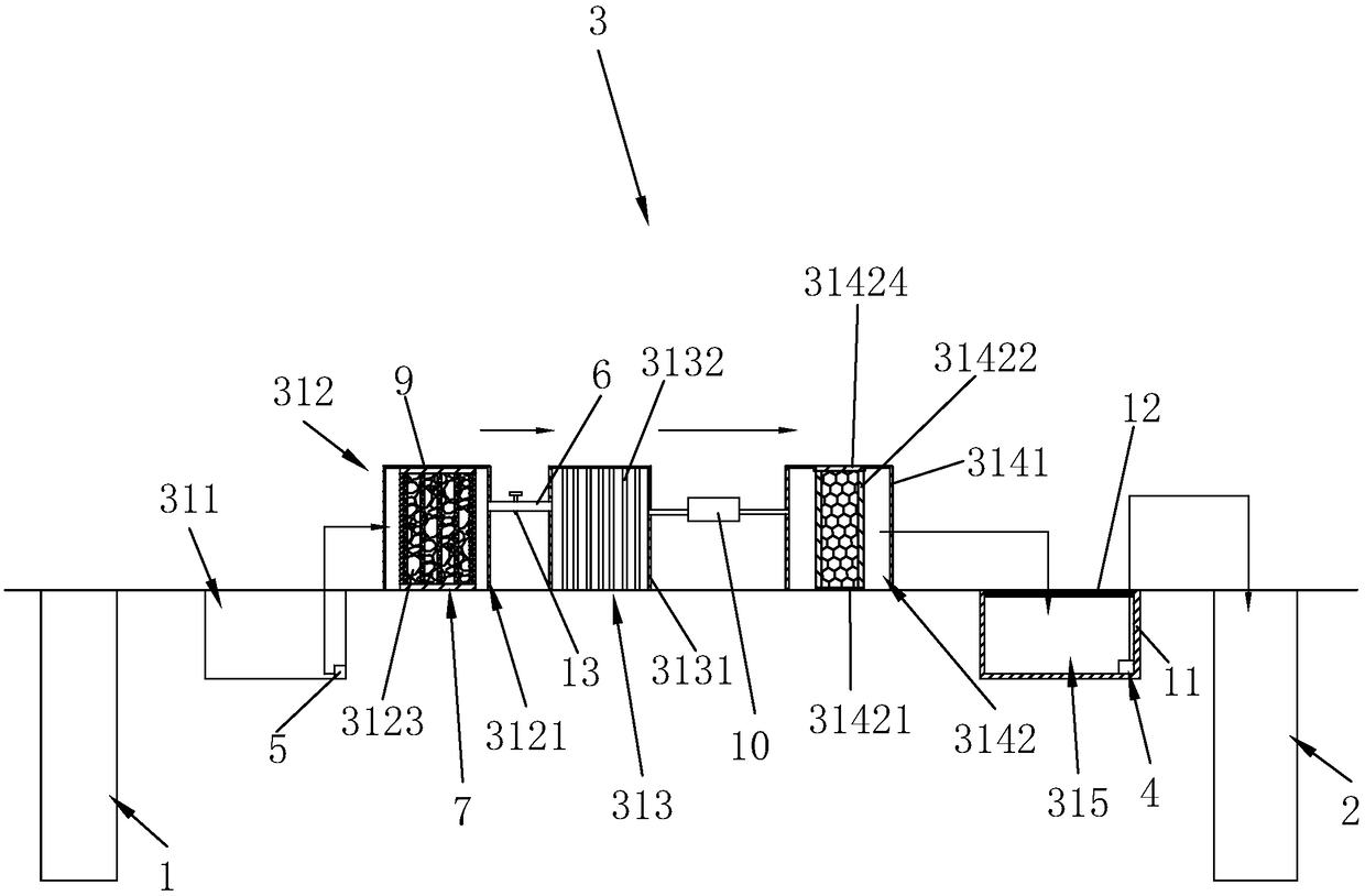
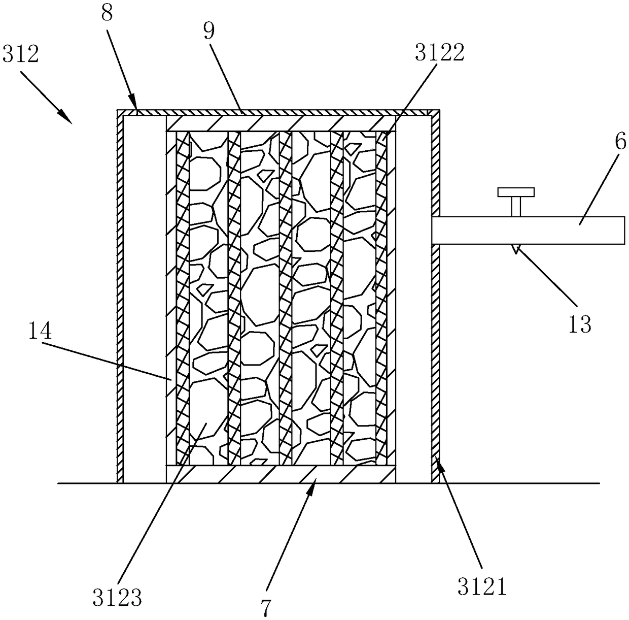
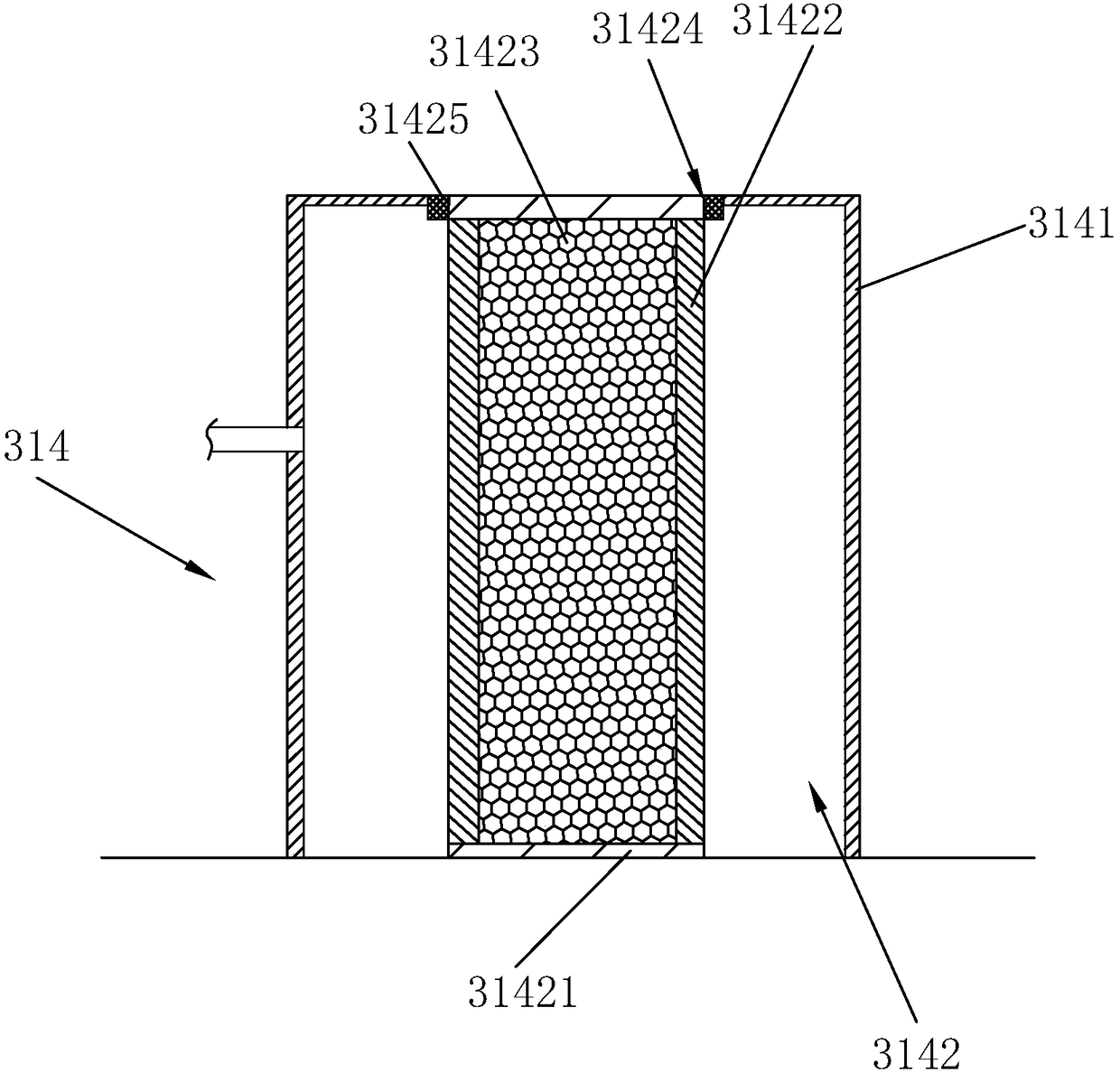
[0035] Such as figure 1 , 2As shown, a foundation pit groundwater recharge system includes a pumping well 1 connected in sequence, a reservoir 311 for storing water pumped out by the pumping well 1, and a filter unit 312 for filtering the water in the reservoir 311 , the sterilizing unit 313 used to sterilize the water filtered by the filter unit 312, the activated carbon adsorption filter unit 314 used to filter the sterilized water, and the recharge tank used to store the wate...


PUM


Abstract

The invention relates to a foundation pit underground water recharge system. The foundation pit underground water recharge system comprises a pumping well, a recharge well and a processing system arranged between the pumping well and the recharge well for processing water pumped from the pumping well. The processing system comprises a water storage pond, a filter unit, a sterilizing unit, an activated carbon adsorptive filter unit and a recharge pond which successively communicate, wherein the water storage pond is used for storing water pumped from the pumping well, the filter unit is used for filtering water in the water storage pond, the sterilizing unit is used for sterilizing water filtered by the filter unit, the activated carbon adsorptive filter unit is used for filtering the sterilized water and the recharge pond is used for storing water filtered by the activated carbon adsorptive filter unit, and a recharge pump for pumping water in the recharge pond to the recharge pump isarranged in the recharge pond. When the pumped water is injected into underground water, the water is processed, so that the water quality of the injected underground water is better than the water quality of the underground water; when the water is injected into the underground water, the water quality of the underground water is unlikely to be polluted.

Description

technical field [0001] The invention relates to a foundation pit groundwater recharge system. Background technique [0002] In foundation pit engineering, in order to ensure that the earth excavation and foundation construction are in a dry state or to improve the stability of the foundation pit slope, the precipitation method is often used to reduce the groundwater in or outside the foundation pit to below the excavation surface, but with the groundwater As the water level decreases, the effective self-gravity stress of the soil below the original water level in the foundation increases, resulting in the consolidation of the foundation soil, which in turn causes uneven settlement, inclination, and cracking of the ground and buildings within the area affected by precipitation, which may endanger its Safe and normal use. [0003] In order to eliminate the impact of foundation pit precipitation on the surrounding environment, the recharge method is usually used to eliminate t...

Claims


Application Information

Patent Timeline
IPC IPC(8): E02D3/10C02F9/08
CPCC02F1/001C02F1/281C02F1/32C02F1/48C02F9/00C02F2201/002C02F2201/007C02F2301/08C02F2303/04E02D3/10
Inventor 陈金碧
Owner 温州华睿建设有限公司
Learn More