
Detergent supply device and wash machine

A supply device and detergent technology, applied in washing devices, other washing machines, applications, etc., can solve problems such as insufficient dilution of liquid detergent, unsmooth siphoning, secondary pollution of clothes, etc., to achieve easy implementation and improvement, and save manufacturing Cost, the effect of enhancing the siphon power

Active Publication Date: 2018-07-06
QINGDAO HAIER WASHING MASCH CO LTD +1
View PDF7 Cites 5 Cited by
  • Summary
  • Abstract
  • Description
  • Claims
  • Application Information

AI Technical Summary

Problems solved by technology

[0004] Although the solution of the prior art can achieve adding additives to the washed clothes according to the set time, because the gap between the inner wall of the siphon column and the outer wall of the siphon hole is very small, and the liquid near the siphon area is of high concentration Relatively large liquid detergent or additives, so the liquid detergent in this area is insufficiently diluted and prone to clogging the siphon hole, resulting in the failure of the siphon to proceed smoothly
If the detergent fails to enter the washing tub during the main wash or pre-wash, it will enter the washing tub during rinsing, causing secondary pollution of the clothes

Method used


Image

  • Detergent supply device and wash machine
  • Detergent supply device and wash machine
  • Detergent supply device and wash machine

Examples


Embodiment 1

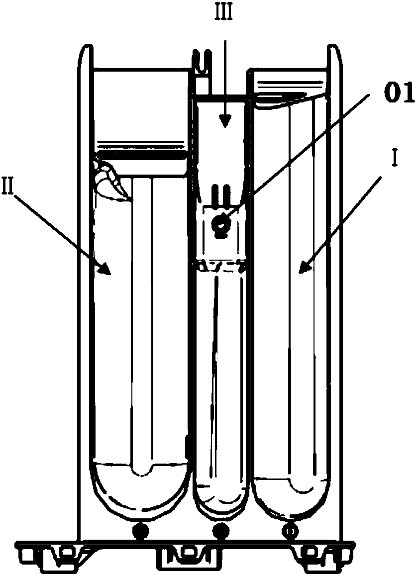
[0058] Figure 5 It is a schematic diagram of the dispenser structure of the detergent supply device of the present invention. The dispenser has three detergent or additive injection chambers, two of which are used to inject liquid detergent or additives, including a siphon structure, and one of the chambers is used for Put softener, the siphon structure of the chamber includes the siphon hole 01 arranged in the liquid detergent delivery chamber and the first siphon cap 03 covering the siphon hole 01, the first siphon cap 03 has the common structure of the prior art siphon cap , the siphon hole 01 is assembled with the first siphon cap 03 and forms a flow channel, and the flow channel communicates with the siphon hole 01; the other chamber is a bleach injection chamber 4 for injecting bleach (of course, it can also be used according to actual needs It is set to put in other liquid detergents or additives, which is not as a limitation to the technical solution), the siphon stru...

Embodiment 2

[0084] The main difference between this embodiment and Embodiment 1 is that the siphon structures in the two chambers for putting liquid detergent or additives all have the structural characteristics described in the present invention, that is, the first siphon cap 03, the second siphon cap 04 and the siphon hole 01 are respectively assembled behind the parts that increase the flow rate of the liquid.

[0085] The rear refers to the flow direction of the liquid in the liquid detergent injection chamber as a reference. The liquid first passes through the parts that increase the liquid flow rate, and then passes through the assembly of the siphon cap and the siphon hole. The parts that increase the liquid flow rate are relatively opposite to the siphon cap and the siphon hole. The assembly point is the rear.

[0086] For other azimuth representations, refer to the above explanations.

[0087] combine Figure 6 , the direction of liquid flow is from A→B, A is the liquid inlet e...


PUM


Abstract

The invention belongs to the technical field of wash machines and particularly relates to a detergent supply device and a wash machine. The detergent supply device includes a siphon structure, and thesiphon structure comprises a siphon hole formed in a liquid detergent putting cavity and a siphon cap covering the siphon hole, and the siphon hole is integrally assembled with the siphon cap and provided with a flow channel; a component for increasing the liquid flow speed is arranged at the rear part of the portion where the siphon cap is assembled with the siphon hole. The detergent supply device can dilute a detergent to the maximum extent, the siphon hole is prevented from being blocked, the siphon power can also be enhanced, and putting of the detergent is much smoother, more uniform and thorough.

Description

technical field [0001] The invention belongs to the technical field of washing machines, and in particular relates to a detergent supply device and a washing machine. Background technique [0002] Currently, washing machines on the market mainly include a drum washing machine in which an inner cylinder rotates around a horizontal axis and a pulsator washing machine in which an inner cylinder rotates around a vertical axis. Among them, the drum washing machine has less wear and tear on clothes, less entanglement between clothes and less water consumption, and is favored by users. [0003] The detergent supply device is an essential part of the drum washing machine. It is set between the water supply valve and the washing drum to provide different laundry detergents or additives at different stages of laundry washing, including washing liquid, bleach, disinfectant, Softener, washing powder, etc. Among them, except for washing powder, which is a solid additive, which can be w...

Claims


Application Information

Patent Timeline
Patent Type & Authority Applications(China)
IPC IPC(8): D06F39/02
CPCD06F39/02D06F39/022F04F10/00
Inventor 王艳丽李丽平黄涛
Owner QINGDAO HAIER WASHING MASCH CO LTD
Learn More