
Roller for ceramic tile printing and preparation process thereof

A technology of rollers and ceramic tiles, applied in printing, printing machines, printing plate preparation, etc., can solve the problems of not being able to meet the production requirements, limited ink loading capacity of the dot screen type, and low speed of screen printing, etc., to achieve convenience Compatible with printing, guaranteed thickness and strength, and stable manufacturing process

Active Publication Date: 2018-07-06
SHANGHAI YUNAN PLATE MAKING
View PDF15 Cites 2 Cited by
  • Summary
  • Abstract
  • Description
  • Claims
  • Application Information

AI Technical Summary

Problems solved by technology

At present, the surface texture of the roller used for ceramic tile surface printing usually adopts screen type, dot mesh type and serpentine mesh type, but the printing speed of the screen type is relatively low and the printing area is small; the dot mesh type The amount of ink loaded is limited, which cannot meet the production requirements; the serpentine mesh roller will form small serpentine textures on the printed surface, and the ink flow on the surface will be uneven

Method used


Image

  • Roller for ceramic tile printing and preparation process thereof
  • Roller for ceramic tile printing and preparation process thereof

Examples


Embodiment 1

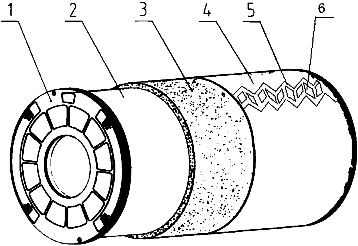
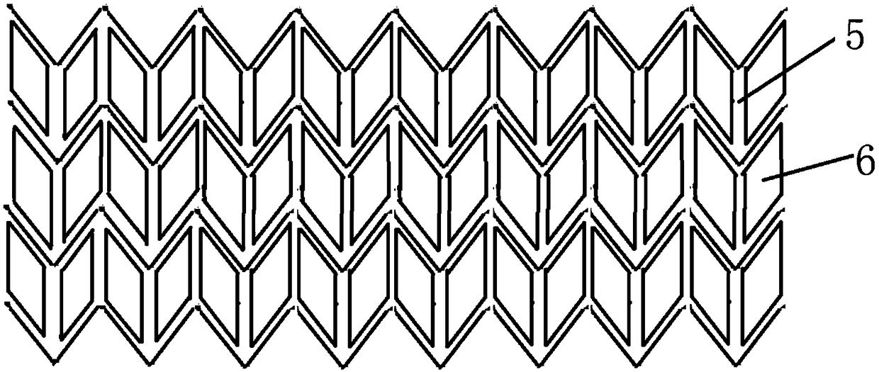
[0023] A roller for ceramic tile printing, its structure is as figure 1 As shown, the roller includes a cylinder body and plugs 1 arranged at both ends of the cylinder body. The cylinder body includes an aluminum plate layer 2, a polyurethane sponge layer 3 and an outer layer of silica gel 4 that are sequentially stacked from inside to outside. The surface of the outer layer of silica gel 4 is provided with There are sawtooth mesh pits 5 distributed along the axial direction of the cylinder, and evenly distributed rhombic mesh pits 6 are arranged in the middle of the sawtooth mesh pits 5. Two sets of opposite sides of the rhombus mesh pits 6 are respectively parallel to the two sides of the serrated edge. figure 1 Only one of the saw-toothed net pits is shown as an illustration. In practice, the surface of the roller is evenly covered with serrated net pits 5. The specific structure of the serrated net pits is as follows: figure 2 shown.

[0024] The zigzag mesh pits adopted...


PUM

PropertyMeasurementUnit
thicknessaaaaaaaaaa
Shore hardnessaaaaaaaaaa

Abstract

The invention relates to a roller for ceramic tile printing and a preparation process thereof. The roller comprises a cylinder body and plugs arranged at the two ends of the cylinder body, wherein thecylinder body comprises an aluminum plate layer, a polyurethane sponge layer and a silica gel outer layer which are sequentially laminated from inside to outside. Mesh pits distributed in the axial direction of the cylinder body are formed in the surface of the silica gel outer layer, the edges of both sides of the mesh pits are serrated, and all the sawteeth of the edges of the mesh pits are ofthe same size; and rhombic mesh pits evenly distributed are formed in the middle of the mesh pits, and the two groups of opposite sides of the rhombic mesh pits are correspondingly parallel to the twosides of the edges of the sawteeth. Compared with the prior art, the roller for ceramic tile printing adopts the jagged mesh pits which are parallel to one another, so that ink carrying amount is large, the ink is not liable to flow in the mesh pits, and thus the leveling property of the roller is increased; another layer of the rhombic mesh pits is arranged in the jagged mesh pits, the ink carrying capacity of the roller is increased, and the thickness and the strength of a screen wall are ensured to facilitate printing; a laser engraving technology is adopted, the engraving of the mesh pitsis more accurate, and the manufacturing technology is more stable.

Description

technical field [0001] The invention relates to the field of printing, in particular to a roller used for ceramic tile printing and a preparation process thereof. Background technique [0002] The product structure in the ceramic tile market has changed. Antique tiles tend to increase. Various effects appear on the surface of ceramic tiles. Some surfaces will have a layer of white and feel old, and some surfaces will have a layer of uneven and transparent bumps. , in order to imitate the texture of natural formation, etc., it is necessary to print a layer of imitation natural texture effect plate after printing the color plate. At present, the surface texture of the roller used for ceramic tile surface printing usually adopts screen type, dot mesh type and serpentine mesh type, but the printing speed of the screen type is relatively low and the printing area is small; the dot mesh type The ink loading capacity is limited, which cannot meet the production requirements; the s...

Claims


Application Information

Patent Timeline
Patent Type & Authority Applications(China)
IPC IPC(8): B41F13/11B41C1/05
CPCB41C1/05B41F13/11Y02P40/60
Inventor 姜红升
Owner SHANGHAI YUNAN PLATE MAKING
Learn More