Integrated robot joint module

A technology of robot joints and joints, which is applied in the field of robots, can solve problems such as single working environment, low load-to-weight ratio, and lack of flexibility, and achieve the effects of optimizing the structure of the whole machine, saving structural space, and improving safety

Pending Publication Date: 2018-07-06
BEIJING RES INST OF PRECISE MECHATRONICS CONTROLS
View PDF0 Cites 14 Cited by
  • Summary
  • Abstract
  • Description
  • Claims
  • Application Information

AI Technical Summary

Problems solved by technology

Although traditional robots are still active in the fields of industrial manufacturing services, the development of the times has made people's needs for production, life, entertainment, medical care and services increasingly novel. Traditional robots cannot meet these requirements in terms of structure, control and intelligence. People need more portable, more integrated, more intelligent robots, and require robots to be able to safely cooperate with people
However, robots that have been widely used in various fields generally have the following problems: (1) The hardware structure is large and heavy, and the mechanical arm is made of rigid steel and other materials, and even equipped with an arm balance mechanism to reduce nonlinear interference. Low self-weight ratio; (2) The working environment is specific and predictable, and the robot base can basically be fixed to complete the task, lacking flexibility; (3) Low integration, thick joints, planetary reduction is generally used, and the motor is installed On the joints, the controller is installed in the control cabinet, and the external control lines are many and miscellaneous. Generally, a large control cabinet is equipped. The power supply, motor drive and motion planning of the robot joints are all realized by the control cabinet. This separation Traditional installation leads to cumbersome maintenance and many potential safety hazards

Method used


Image

  • Integrated robot joint module
  • Integrated robot joint module
  • Integrated robot joint module

Examples


Embodiment Construction

[0035] In order to make the object, technical solution and advantages of the present invention clearer, the implementation manner of the present invention will be further described in detail below in conjunction with the accompanying drawings.

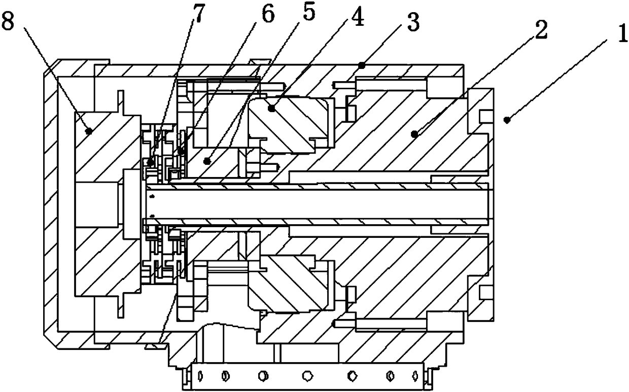
[0036] An integrated robot joint module, including joint output member 1, harmonic reducer 2, joint housing 3, drive motor body 4, brake mechanism 5, motor input encoder 6, joint output encoder 7, integrated circuit modules 8, such as figure 1 shown.

[0037]The joint output component 1 is used to connect the external actuator or load; the harmonic reducer 2 is used to adjust the rotation speed of the joint output component 1; the joint shell 3 is used to fix the harmonic reducer 2, the driving motor body 4, the brake mechanism 5, and the motor The input end encoder 6, the joint output end encoder 7 and the integrated circuit module 8; the drive motor main body 4 is used to drive the harmonic reducer 2 according to the instruction of ...


PUM


Abstract

The invention provides an integrated robot joint module. The integrated robot joint module comprises a joint output component, a harmonic reducer, a joint shell, a driving motor main body, a brake mechanism and an integrated circuit module; the joint output component is used for being connected with an external execution mechanism or a load; the harmonic reducer is used for adjusting the rotatingspeed of the joint output component; the joint shell is used for fixing the harmonic reducer and driving the motor main body, the brake mechanism and the integrated circuit module, and the driving motor main body is used for driving the harmonic reducer according to the instruction of the integrated circuit module; the brake mechanism is used for holding the driving motor main body according to aninstruction of the integrated circuit module; and the integrated circuit module drives the working state of the motor main body according to an instruction of an external upper computer, and the working state of the joint output component is used for driving the driving motor main body.

Description

technical field [0001] The invention relates to a module, in particular to an integrated robot joint module, which belongs to the field of robots. Background technique [0002] Since its birth, robots have been widely used in various fields, such as vehicle assembly, mechanical parts processing, palletizing and handling, surface grinding, paint spraying, plate welding, serving medical and military equipment and other industries are all hot industries of robots. Although traditional robots are still active in the fields of industrial manufacturing services, the development of the times has made people's needs for production, life, entertainment, medical care and services increasingly novel. Traditional robots cannot meet these requirements in terms of structure, control and intelligence. People need more portable, more integrated, and more intelligent robots, and require robots to be able to safely cooperate with people. However, robots that have been widely used in various ...

Claims


Application Information

Patent Timeline
IPC IPC(8): B25J17/00B25J19/00H02K7/10
CPCH02K7/10B25J17/00B25J19/00
Inventor 远桂方郭喜彬侍威李鹏飞郑继贵
Owner BEIJING RES INST OF PRECISE MECHATRONICS CONTROLS
Why Eureka
Try Eureka