
Impact crusher for ore mining

An impact crusher and mining technology, applied in the field of mining and quarrying equipment, can solve problems such as the inability to change the degree of crushing of stones, the jamming of stones between the conveyor belt and the rotor, and the damage of the transmission belt, so as to increase buffering performance and increase wear. Strength and prolonging the service life

Pending Publication Date: 2018-07-06
ANHUI UNIV OF SCI & TECH
View PDF0 Cites 9 Cited by
  • Summary
  • Abstract
  • Description
  • Claims
  • Application Information

AI Technical Summary

Problems solved by technology

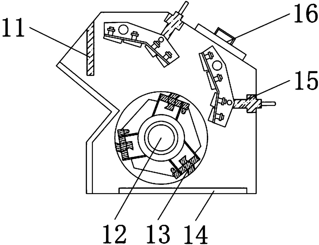
[0003] In mining and quarrying, the crusher is usually used to crush the larger stones for preliminary treatment. The striking plate device inside the traditional crusher is fixed to the upper panel of the impact crusher with bolts, and the stones are crushed in the rotor assembly. When rebounding to the counterattack plate, the position of the counterattack frame cannot be changed, so that the degree of crushing of the stone cannot be changed. The stone needs to be processed twice, which increases the cost. In the connection between the conveyor belt and the rotor, because there is no protective device, it is very easy to Causing stones stuck between the conveyor belt and the rotor, causing damage to the conveyor belt

Method used


Image

  • Impact crusher for ore mining
  • Impact crusher for ore mining
  • Impact crusher for ore mining

Examples


Embodiment Construction

[0019] The following will clearly and completely describe the technical solutions in the embodiments of the present invention with reference to the accompanying drawings in the embodiments of the present invention. Obviously, the described embodiments are only some, not all, embodiments of the present invention. Based on the embodiments of the present invention, all other embodiments obtained by persons of ordinary skill in the art without making creative efforts belong to the protection scope of the present invention.

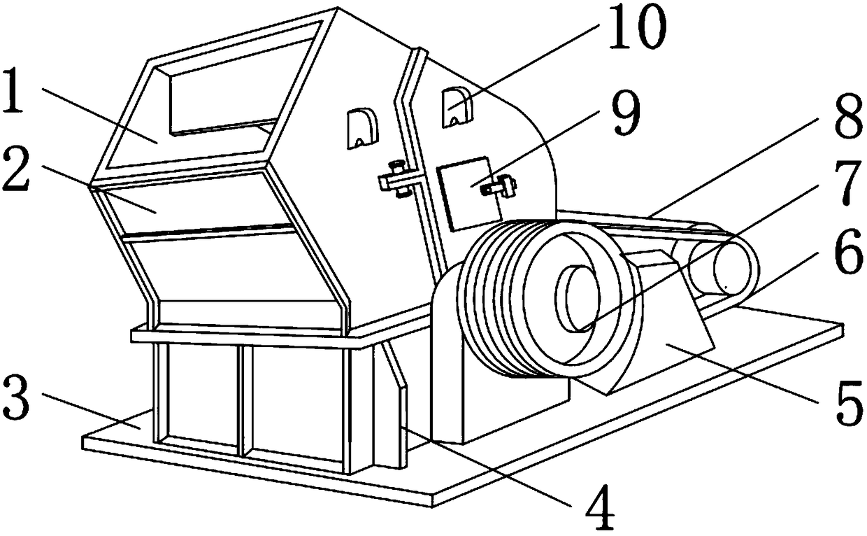
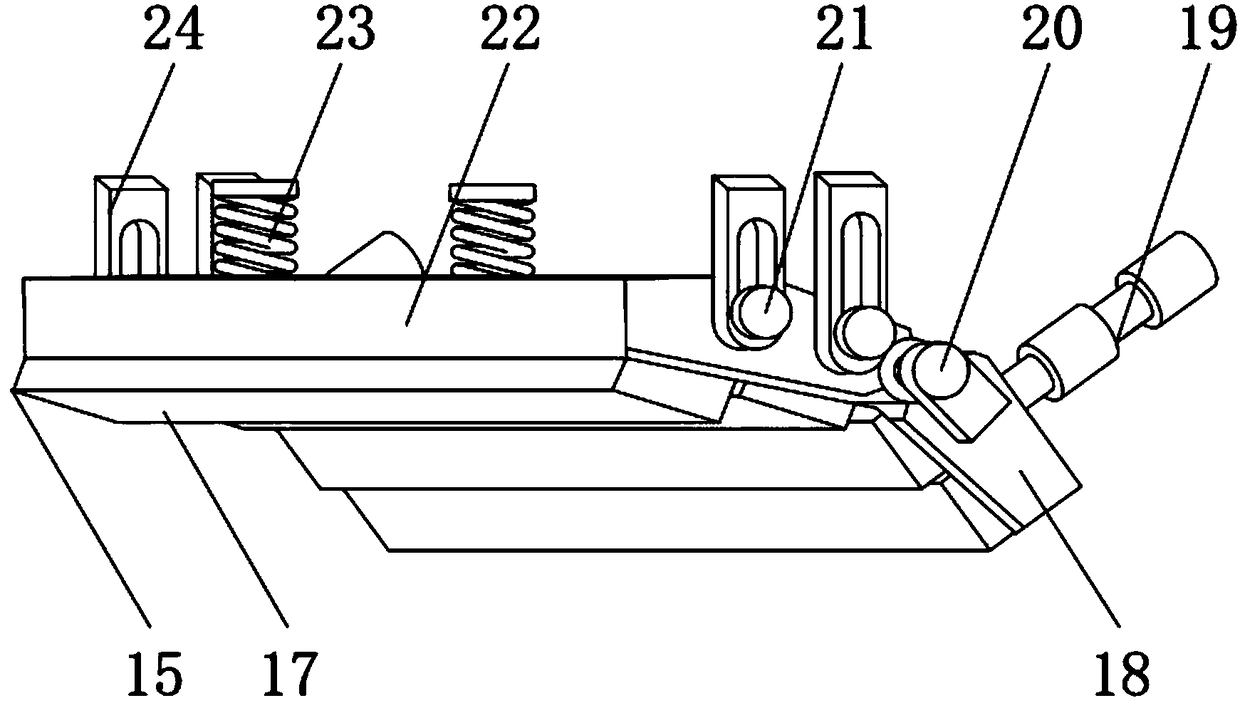
[0020] see Figure 1-4 As shown, the present invention provides a technical solution: an impact crusher for mining and quarrying, comprising a fuselage shell 2, the lower end surface of the fuselage shell 2 is fixedly connected with a bottom plate 3, and the side end surface of the fuselage shell 2 is fixedly connected There is a fixed mounting plate 4, the side end surface of the body shell 2 away from the fixed mounting plate 4 is rotatably connected with a ...


PUM


Abstract

The invention discloses an impact crusher for ore mining. The impact crusher for ore mining comprises a housing, wherein a bottom plate is fixedly connected to the lower end surface of the housing; afixing mounting plate is fixedly connected to the side end surface of the housing; a transmission wheel is rotatably connected to one side, deviated from the fixing mounting plate, of the side end surface of the housing; a conveyor belt is rotatably connected to the outer end surface of the transmission wheel; a motor is rotatably connected to the inner end surface of the conveyor belt; a detecting door is rotatably connected to one side, deviated from the transmission wheel, of the side end surface of the housing; a fixing block is fixedly connected to one side, deviated from the detecting door, of the side end surface of the housing; a feeding port is formed in the upper end surface of the housing; a conveyor belt protecting body is in sliding connection with the upper end surface of thebottom plate; a discharging port is formed in the lower end surface of the housing; a rotating shaft is fixedly connected to the side end surface of the transmission wheel. According to the impact crusher for the ore mining, the conveyor belt is mounted for protecting a crusher body; and the problem that a conveyor belt of a traditional crusher is easily damaged by ore can be solved.

Description

technical field [0001] The invention relates to the technical field of mining and quarrying equipment, in particular to an impact crusher for mining and quarrying. Background technique [0002] Impact crusher is also called impact crusher. It is mainly used for metallurgy, chemical industry, building materials, hydropower and other materials processing that often need to be relocated, especially for the operation of mobile stone materials such as highways, railways, and hydropower projects. It can be processed according to the raw materials Various configurations are used depending on the type, scale and material requirements of the finished product. [0003] In mining and quarrying, the crusher is usually used to crush the larger stones for preliminary treatment. The striking plate device inside the traditional crusher is fixed to the upper panel of the impact crusher with bolts, and the stones are crushed in the rotor assembly. When rebounding to the counterattack plate, ...

Claims


Application Information

Patent Timeline
IPC IPC(8): B02C13/09B02C13/282B02C13/31
CPCB02C13/095B02C13/282B02C13/31
Inventor 史先春
Owner ANHUI UNIV OF SCI & TECH
Learn More