
Special mounter for shielding cap

A placement machine and shielding cover technology, which is applied in the field of special placement machines for shielding covers, can solve the problems of stability and precision that are difficult to meet the mounting accuracy, low precision, and large identification errors of shielding covers, so as to maintain the synchronization of suction nozzles Workability, ensure feeding accuracy, and improve placement efficiency

Pending Publication Date: 2018-07-03
广东木几智能装备有限公司
View PDF0 Cites 9 Cited by
  • Summary
  • Abstract
  • Description
  • Claims
  • Application Information

AI Technical Summary

Problems solved by technology

The shape of the shielding cover has certain irregularities due to size changes. At present, the general-purpose placement machines in the market cannot be processed and placed, and only some of the latest improved foreign placement machines can be placed.
It has obvious defects: ①Due to the large variation in the mounting size of the shielding cover, the distance between the suction heads of the machine is not enough, and many of them can only be used with a single head, so the production efficiency is low; Low; ③The stability and precision of the spline shaft, synchronous wheel, and belt mechanism used in the general-purpose placement head are difficult to meet the placement accuracy

Method used


Image

  • Special mounter for shielding cap
  • Special mounter for shielding cap
  • Special mounter for shielding cap

Examples


Embodiment Construction

[0039] In order to more clearly illustrate the embodiments of the present invention or the technical solutions in the prior art, the following will briefly introduce the drawings that need to be used in the description of the embodiments or the prior art. Obviously, the accompanying drawings in the following description are only These are some embodiments of the present invention. Those skilled in the art can also obtain other drawings based on these drawings without creative work.

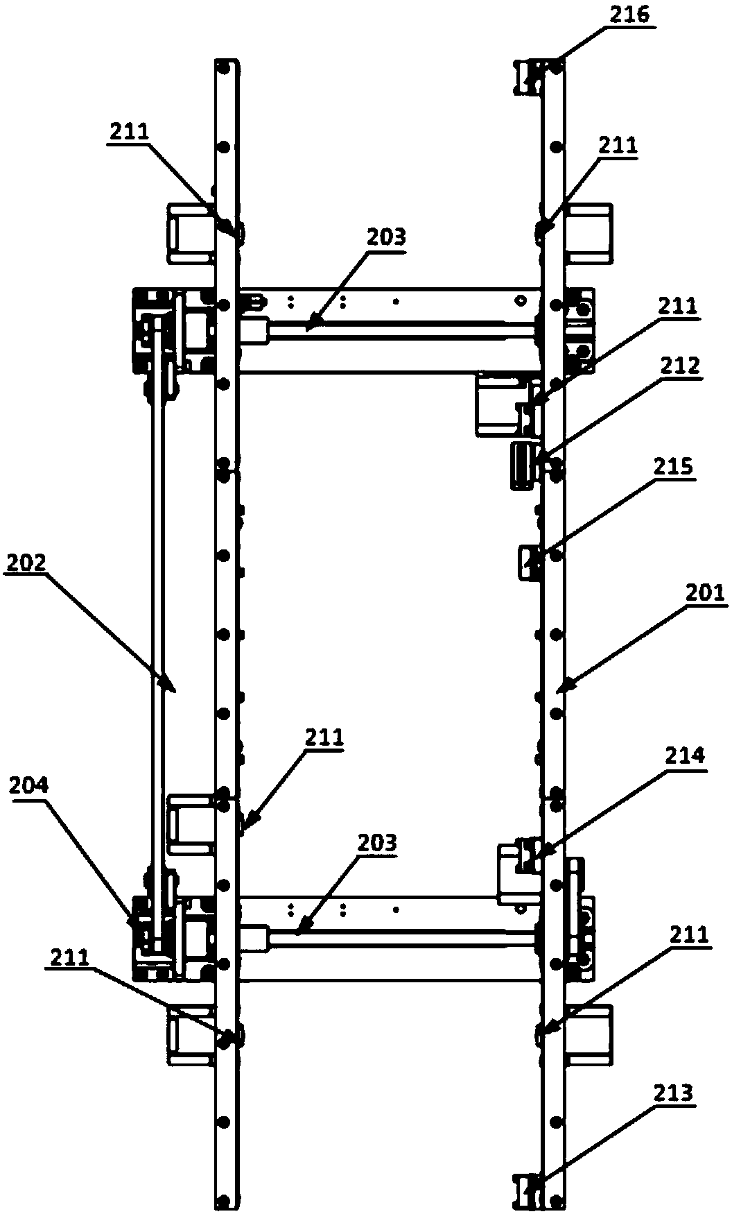
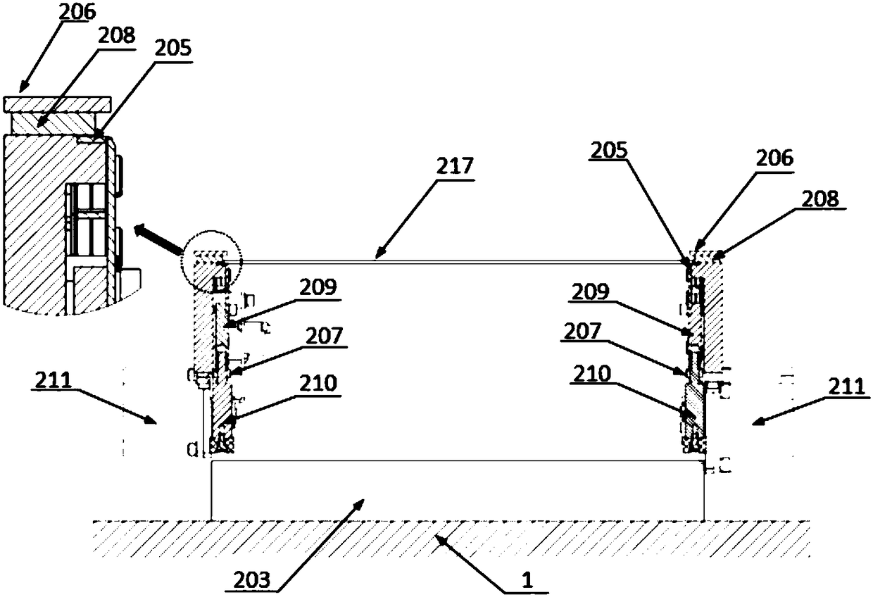
[0040] Such as Figure 1 to Figure 7 As shown, a special mounter for shielding covers includes a main body frame 1 and a PCB transmission assembly 2 arranged on the main body frame 1, a Y-axis arch assembly 3, an X-axis arch assembly 4, a placement head assembly 5, Feeding platform 6,

[0041]The PCB transfer assembly 2 is arranged in the middle of the top of the main frame 1, and the PCB transfer assembly 2 includes a fixed side 201 and a movable side 202,

[0042] The fixed side 201 is fixed o...


PUM


Abstract

The invention discloses a special mounter for a shielding cap, which comprises a main frame, a board conveying device, a Y-axis arch frame assembly, an X-axis arch frame assembly, a mounting head assembly and a feeding platform, wherein the moving side edge of the board conveying device is provided with a width regulation motor; and the Y-axis arch frame assembly and the X-axis arch frame assemblyform an XY moving platform of the mounting head assembly. Through arranging the width regulation motor, a stop block, a board entering sensor, a mounting sensor, a board exiting sensor and the like,the size of the shielding cap can be matched, the width of the board conveying device is adjusted, and the board conveying working position is high in accuracy and safety; through arranging the special mounting head assembly, the size of the shielding cap can be matched thoroughly, nozzle synchronous working can be kept, and the mounting efficiency is effectively enhanced; through arranging a coupling to be connected with a motor shaft and a shaft, elastic movement in the moving process is avoided, and the mounting accuracy and the stability are ensured; and through arranging the special feeding platform, the feeding accuracy is ensured, and the feeding efficiency is improved.

Description

technical field [0001] The invention relates to a placement machine, in particular to a special placement machine for shielding covers. Background technique [0002] With the rapid development of electronic information technology, the requirements for the efficiency and stability of various types of electronic products are getting higher and higher, and the equipment related to information communication has higher requirements for the efficiency and stability of information transmission. Therefore, a large number of electronic products will design various metal shielding covers according to the signal distribution to reduce external interference and improve the stability of electronic products. [0003] The placement machine is usually composed of an XY precision positioning platform and a placement head with a placement function. The material rack is usually fixedly installed on one side of the chip mounter body. In each working cycle of the chip mounter, the chip head mus...

Claims


Application Information

Patent Timeline
IPC IPC(8): H05K3/30
CPCH05K3/30
Inventor 吴志达程治国吴克桦彭涛
Owner 广东木几智能装备有限公司
Learn More