
Left portion positioning and clamping tool for automobile left and right side inner plate front assembly

A side wall inner panel, positioning and clamping technology, which is applied in the direction of auxiliary devices, manufacturing tools, metal processing equipment, etc., can solve the problems of difficulty in ensuring the overall accuracy, high cost investment, and affecting the efficiency of production and processing, so as to improve the effective efficiency and product quality, high degree of automation, and reasonable structural design

Active Publication Date: 2018-07-03
ANHUI DACHANG TECH
View PDF5 Cites 0 Cited by
  • Summary
  • Abstract
  • Description
  • Claims
  • Application Information

AI Technical Summary

Problems solved by technology

The traditional processing of the front assembly of the left and right side panels of automobiles mostly adopts multi-process, multi-station positioning, clamping, welding and fixing methods. There is a problem with the forming of the front assembly of the board. However, due to the multi-process, multi-station, and multiple clamping and positioning methods, the overall accuracy after processing is difficult to guarantee. Often, the inspection fails after the overall welding is formed, and it needs to be returned to the factory for repair. Seriously affect the efficiency of production and processing
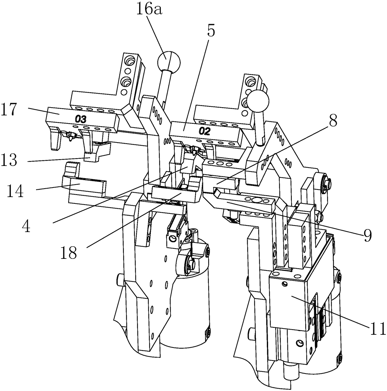
For example, the left part of the front assembly of the left and right side panels of the automobile needs to be welded with two lugs 21 and 22 during the production process. The traditional processing method is to use two independent fixtures, that is, two processes, It is difficult to ensure the relative accuracy between the two lugs 21 and 22 by clamping twice, so the disassembly method is difficult, and the space occupied by the two tooling is relatively large, and the cost of manufacturing is also relatively large.

Method used


Image

  • Left portion positioning and clamping tool for automobile left and right side inner plate front assembly
  • Left portion positioning and clamping tool for automobile left and right side inner plate front assembly
  • Left portion positioning and clamping tool for automobile left and right side inner plate front assembly

Examples


Embodiment Construction

[0019] In order to make the technical means, creative features, goals and effects achieved by the present invention easy to understand, the present invention will be further elaborated below.

[0020] Such as Figure 1 to Figure 4 As shown, a left positioning and clamping tool for the front assembly of the left and right side panels of the automobile, including the left automatic positioning clamp, distributed on the right side of the left automatic positioning clamp and cooperated with the left automatic positioning clamp Position the clamped left auxiliary clamp. The invention has a reasonable structural design, uses a set of clamps to realize the positioning and clamping of all parts of the left part of the left and right side panel front assembly 20 of the entire automobile, and solves the traditional multi-process, multi-position, and multiple clamping The positioning method has the problems of complex operation, low precision and low efficiency, which ensures the moldin...


PUM


Abstract

The invention relates to a left portion positioning and clamping tool for an automobile left and right side inner plate front assembly. The tool comprises a left end automatic positioning and clampingdevice and a left auxiliary clamping device which is distributed on the right side of the left end automatic positioning and clamping device and is matched with the left end automatic positioning andclamping device to achieve positioning and clamping. The tool is reasonable in structural design and high in space utilization rate; clamping of the left portion of the front part assembly of the automobile left and right side inner plate front assembly can be achieved through a tool clamp, it is guaranteed that two lug bases can be accurately positioned and clamped, an external welding robot canconveniently and automatically conduct welding, the effective efficiency and the product quality are greatly improved, and the automation degree is high.

Description

technical field [0001] The invention relates to the technical field of production and processing of automobile parts, in particular to a left positioning and clamping tool for the front assembly of left and right side wall inner panels of automobiles. Background technique [0002] As we all know, the front assembly of the left and right side panels of the car is one of the important components of the car. Since it is welded after splicing multiple structures, it requires high overall welding accuracy and dimensional accuracy. The traditional processing of the front assembly of the left and right side panels of automobiles mostly adopts multi-process, multi-station positioning, clamping, welding and fixing methods. There is a problem with the forming of the front assembly of the board. However, due to the multi-process, multi-station, and multiple clamping and positioning methods, the overall accuracy after processing is difficult to guarantee. Often, the inspection fails aft...

Claims


Application Information

Patent Timeline
IPC IPC(8): B23K37/04
CPCB23K37/0443
Inventor 张同意钟华山
Owner ANHUI DACHANG TECH
Learn More