
Linkage locking anti-rebounding civil defense door utilizing fluid pressure

A fluid pressure, civil air defense door technology, applied to non-mechanical transmission-operated locks, building locks, door/window accessories, etc. Stable and reliable, good synchronization, simple operation effect

Pending Publication Date: 2018-06-29
张阳鑫
View PDF3 Cites 4 Cited by
  • Summary
  • Abstract
  • Description
  • Claims
  • Application Information

AI Technical Summary

Problems solved by technology

The link mechanism in the prior art is relatively complicated, which makes it difficult to manufacture, process, install and debug, and use and maintain. At the same time, the traditional civil air defense door uses a multi-link mechanism to lock, and after a long period of use, the multi-link mechanism It is easy to produce corrosion and rust, which makes the operation difficult, and the virtual displacement caused by the wear of the connecting rod is not conducive to use; in addition, when it is subjected to rebound force, the multi-link mechanism is easily damaged, resulting in higher maintenance costs and even the whole machine. The door is scrapped

Method used


Image

  • Linkage locking anti-rebounding civil defense door utilizing fluid pressure
  • Linkage locking anti-rebounding civil defense door utilizing fluid pressure
  • Linkage locking anti-rebounding civil defense door utilizing fluid pressure

Examples


Embodiment 1

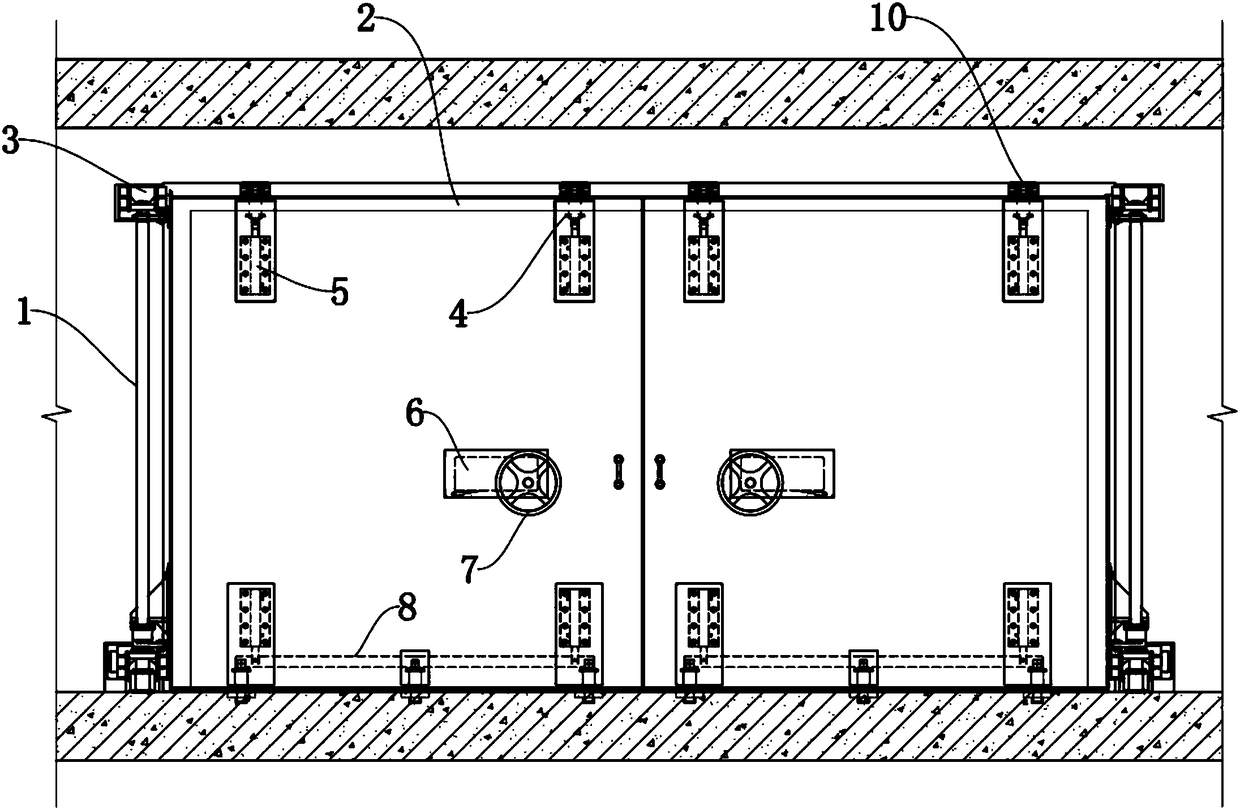
[0040] Such as figure 1 , figure 2 As shown, this embodiment discloses a linkage locking anti-rebound civil air defense door using fluid pressure, including a door frame 1, a door leaf 2, a fluid pressure system arranged on the door leaf 2, and a lock head 4 for switching.

[0041]The door frame 1 is fixed on the wall, and the door leaf 2 is connected to the door frame 1 through the hinge 3. The fluid pressure system includes a pump 6, a reversing valve 12, pipelines and multiple synchronously operating double-acting pressure cylinders 5, and the pump 6 communicates with Reversing valve 12. The reversing valve 12 communicates with the double-acting pressure cylinder 5 through a pipeline; the double-acting pressure cylinder 5 includes a cylinder body and a piston rod, and the cylinder body is fixed on the door leaf 2 or in the door leaf 2 through the cylinder seat 501; the lock head 4 is connected with the double-acting pressure cylinder 5. The lock head 4 includes a lock bo...

Embodiment 2

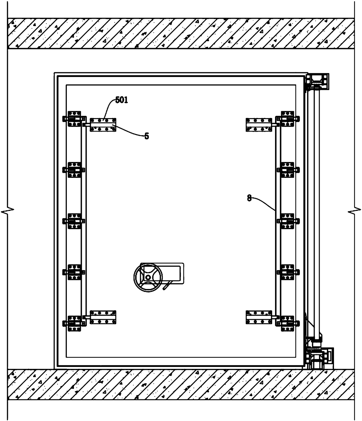
[0052] Such as image 3 As shown, this embodiment discloses a linkage locking anti-rebound civil air defense door utilizing fluid pressure, including a door frame 1, a door leaf 2 arranged in the door frame 1, a fluid pressure system arranged on the door leaf 2 and a lock head for switching 4.

[0053] The structure and connection relationship of each part in this embodiment are the same as in Embodiment 1, the difference is:

[0054] In this embodiment, the double-acting pressure cylinder 5 is arranged horizontally, the piston rod corresponds to the lateral movement, the lock head 4 connected to the double-acting pressure cylinder 5 is arranged horizontally, and the lock cylinder 402 corresponds to the lateral movement. Two double-acting pressure cylinders 5 are respectively arranged on the left and right sides of the door leaf 2, and a reinforcing plate is arranged between the double-acting pressure cylinder 5 and the door leaf 2, and the double-acting pressure cylinder 5, ...

Embodiment 3

[0057] Such as Figure 4 As shown, this embodiment discloses a linkage locking anti-rebound civil air defense door utilizing fluid pressure, including a door frame 1, a door leaf 2 arranged in the door frame 1, a fluid pressure system arranged on the door leaf 2 and a lock head for switching 4.

[0058] The structure and connection relationship of each part in this embodiment are the same as in Embodiment 1, the difference is:

[0059] In this embodiment, the lock core 402 and the piston rod are connected through a shaft-hole matching structure, and fastening bolts are provided at the connection for fastening. In this matching structure, the lock core 402 is provided with a hole, the end of the piston rod is provided with a shaft that fits into the hole, and the lock core 402 is provided with a screw hole communicating with the hole, and the fastening bolt is located in the screw hole and press against the shaft; or the end of the lock cylinder 402 is provided with a shaft, ...


PUM


Abstract

The invention relates to protective equipment in the field of civil defense engineering and national defense engineering and discloses a linkage locking anti-rebounding civil defense door utilizing fluid pressure. The linkage locking anti-rebounding civil defense door comprises a door frame, door leaves, fluid pressure systems arranged on the door leaves, and lock heads used for opening and closing. The door leaves and the door frame are connected through hinges; each fluid pressure system comprises a pump, a reversing valve, pipelines and a plurality of double-effect pressure cylinders; the pumps communicate with the reversing valves, and the reversing valves communicate with the double-effect pressure cylinders through pipelines; the lock heads are in matched connection with the double-effect pressure cylinders and comprise lock bodies and sliding lock cylinders; lock boxes matched with the lock cylinders correspondingly are arranged on the door frame; and limiting grooves are formedin the lock cylinders, and limiting blocks in sliding fit with the limiting grooves are arranged on the lock bodies. The fluid pressure system in the linkage locking anti-rebounding civil defense door can keep the stable pressure in a long term, and the pressure is transmitted through fluids, so that operation is easier, linkage is more stable and more reliable, and virtual displacement is avoided; and synchronous linkage arrangement is conducted, and thus synchronization of the multiple lock heads at the time of executing unlocking and locking is better; and therefore, the locking anti-rebounding civil defense door is worth popularizing.

Description

technical field [0001] The invention relates to protective equipment in the field of civil air defense engineering and national defense engineering, in particular to a linkage locking anti-bounce civil air defense door utilizing fluid pressure. Background technique [0002] Civil air defense projects refer to the underground protective buildings built separately to ensure the shelter of personnel and materials in wartime, civil air defense command, medical rescue, etc., and the basements built in combination with ground buildings that can be used for air defense in wartime. The civil air defense door belongs to the protective equipment, which has the function of preventing shock waves and biological and chemical weapons, and is used in the entrances and exits, vents and other parts of civil air defense projects. [0003] In the prior art, commonly used civil air defense doors are composed of door leaf, door frame, hinges, locks and other main mechanisms. The door leaf and do...

Claims


Application Information

Patent Timeline
IPC IPC(8): E06B5/10E05C9/00E05B51/02
CPCE05B51/02E05C9/00E06B5/10E05Y2900/132E05B2051/026
Inventor 张阳鑫
Owner 张阳鑫
Learn More