
Efficient grain drying equipment

A drying equipment and grain technology, applied in the direction of drying and preserving seeds, etc., can solve the problems of automatic turning over, poor drying effect, poor impurity removal effect, etc., to shorten the drying time and structure Simple, low-cost effect

Inactive Publication Date: 2018-06-29
郑州龙威电气安装有限公司
View PDF0 Cites 2 Cited by
  • Summary
  • Abstract
  • Description
  • Claims
  • Application Information

AI Technical Summary

Problems solved by technology

[0005] Based on the above technical problems, the present invention provides a high-efficiency grain drying equipment, which solves the technical problems in the prior art that the grain cannot be turned over automatically during the drying process, resulting in poor drying effect and low efficiency.
[0006] It solves the technical problem that the impurity removal effect of the grain in the prior art is not good during the drying process, resulting in more impurities in the grain

Method used


Image

  • Efficient grain drying equipment
  • Efficient grain drying equipment
  • Efficient grain drying equipment

Examples


Embodiment 1

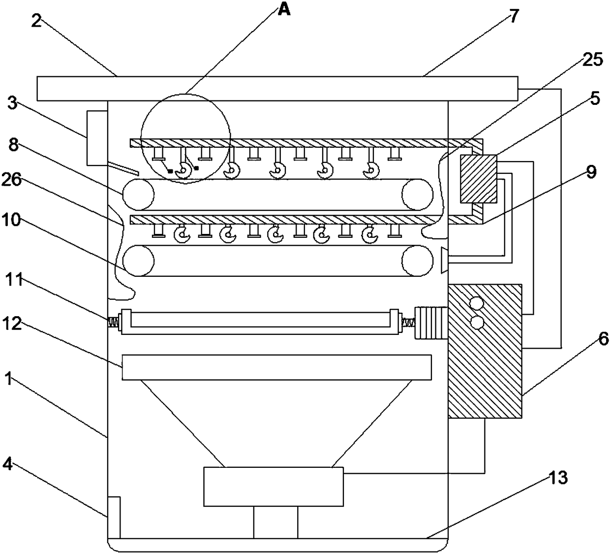
[0025] Such as Figure 1-3 As shown, a high-efficiency grain drying equipment includes an equipment main body 1 and a solar panel 2 arranged above the equipment main body 1. One side of the equipment main body 1 is provided with a material inlet 3 and a material outlet 4, and the opposite surface is provided with There is a blower 5 and a controller 6. The controller 6 is located at the lower end of the blower 5 and is electrically connected to the solar panel 2. The main body of the device 1 is provided with a first air supply pipe 7 and a first transmission device in sequence from top to bottom. 8. The second air supply pipe 9, the second conveying device 10, the vibrating device 11, the drying device 12 and the screen 13;

[0026] The first air supply pipe 7 and the second air supply pipe 9 are respectively connected with two air outlet ends of the air blower 5, and the air inlet end of the air blower 5 is positioned at the right end of the second conveying device 10, and t...

Embodiment 2

[0029] Based on Embodiment 1, the mesh radius of the screen 13 is smaller than that of the grain.

[0030] The sieve 13 in the present embodiment plays a role of screening and filtering, and the impurities whose volume is smaller than the grain are filtered and fall into the sieve 13, and the grain stays above the sieve 13.

Embodiment 3

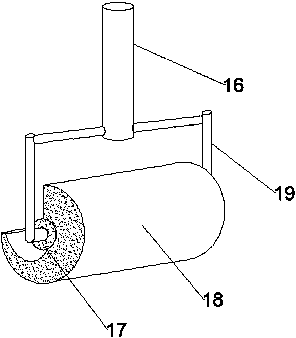
[0032] Based on Embodiment 1, the opening of the rotating drum 18 of the turning device 15 on the first air supply pipe 7 faces the direction of the feed port 3, and the rotating drum of the turning device 15 on the second air supply pipe 9 The opening of 18 is towards the blower 5 direction.

[0033] In this embodiment, the motor on the first air supply pipe 7 drives the drum to rotate clockwise, and the motor on the second air supply pipe 9 drives the drum to rotate counterclockwise, so as to ensure that the openings of the drum 18 are all facing the grain conveying direction, which can realize Roll the grain into the drum to turn the grain over.


PUM


Abstract

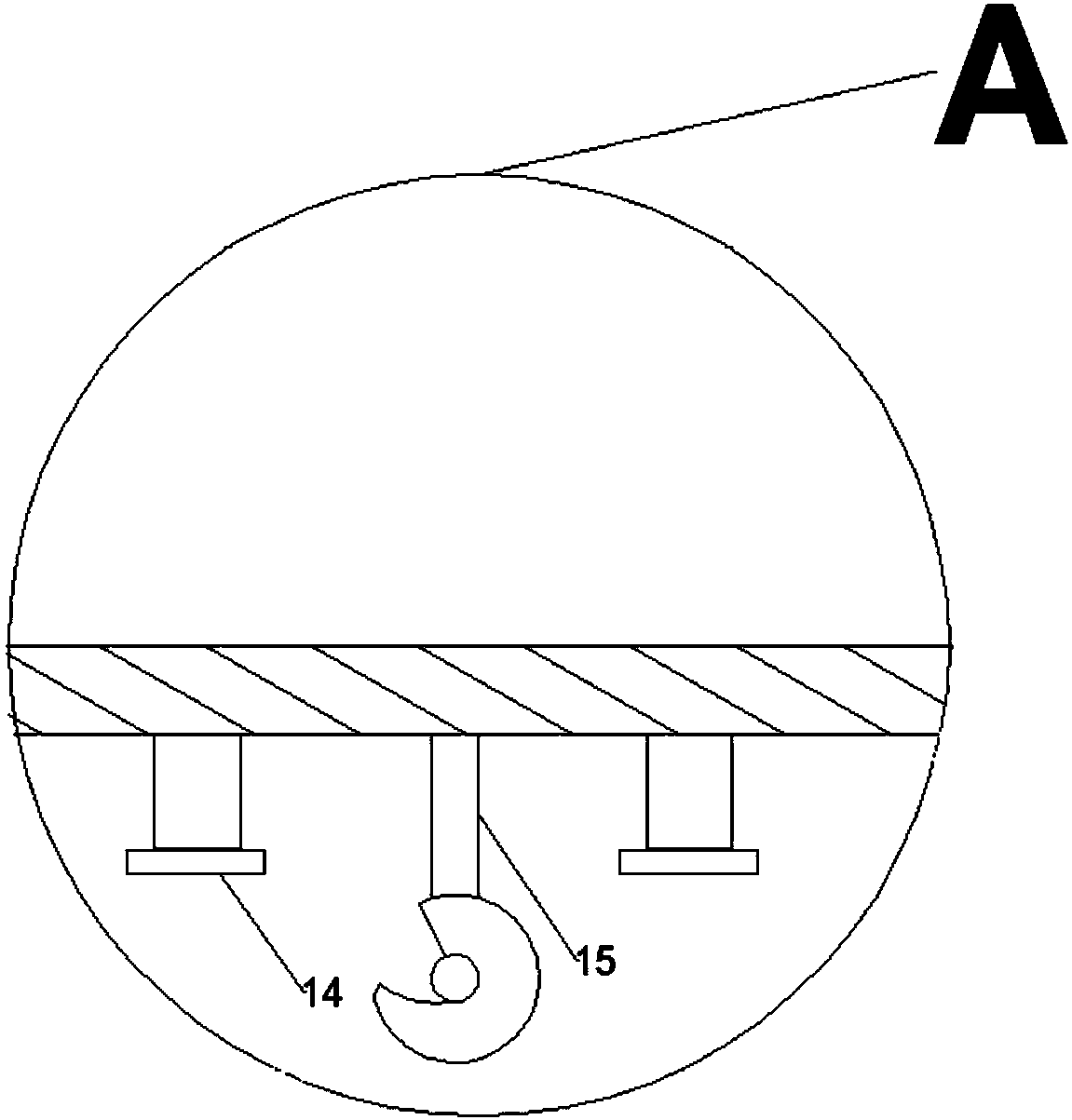
The invention discloses efficient grain drying equipment and relates to the field of crop processing. The equipment comprises an equipment body and a solar mainboard arranged above the equipment body.A first air supply pipe, a first conveying device, a second air supply pipe, a second conveying device, a vibration device, an air drying device and a screen are sequentially arranged in the equipment body from top to bottom; air outlet pipes and turnover devices are arranged on the first air supply pipe and the second air supply pipe and sequentially arranged in a staggered manner; each turnoverdevice comprises a support rod and a rotating shaft, the rotating shaft is connected with the support rod through a connecting shaft, a motor is arranged in the rotating shaft, a rotating drum is fixed outside the rotating shaft, and the cross section of the rotating drum is crescent-shaped. The technical problems of poor drying effect and low efficiency due to the fact that grains cannot be automatically turned during drying in the prior art are solved.

Description

technical field [0001] The invention relates to the field of crop processing, in particular to a high-efficiency grain drying equipment. Background technique [0002] In order to preserve the grain for a long time, the most important thing is to dry the grain. As we all know, when the temperature and humidity conditions in the environment of the grain meet the growth and reproduction of microorganisms, mildew will occur. That is to say that moisture and temperature are two important factors for the reproduction of microorganisms such as mold in grains (i.e. grain mildew). In general, controlling the grain moisture below the safe moisture level may prevent the grain from going moldy. [0003] The traditional method of reducing grain moisture is the spontaneous combustion drying method. In the main grain producing areas, due to the large output and insufficient drying space, the moisture in the grain purchased by the grain depot often exceeds the safe water content, which is...

Claims


Application Information

Patent Timeline
Patent Type & Authority Applications(China)
IPC IPC(8): A23B9/08
CPCA23B9/08
Inventor 杨伯军
Owner 郑州龙威电气安装有限公司
Learn More