
Die bonder

A technology of chip bonding and bonding layer, applied in welding equipment, laser welding equipment, electrical components, etc., can solve problems such as difficulty and productivity deterioration

Active Publication Date: 2018-06-26
DISCO CORP
View PDF6 Cites 4 Cited by
  • Summary
  • Abstract
  • Description
  • Claims
  • Application Information

AI Technical Summary

Problems solved by technology

[0005] In the case of assembling LEDs as a module using the above-mentioned die bonding machine, it takes time and effort to bond the divided LEDs to the module chip one by one. In recent years, LEDs have been miniaturized, so there is a problem that productivity deteriorates.
[0006] In addition, the miniaturization of devices such as ICs and LSIs has gradually progressed according to the size of one side of 100 μm or less and 50 μm or less, and the thickness is also thinner than 20 μm. It is extremely difficult to selectively pick up devices on a wafer that has been divided into individual devices and bond them on a wiring substrate

Method used


Image

  • Die bonder
  • Die bonder
  • Die bonder

Examples


Embodiment Construction

[0026] Hereinafter, preferred embodiments of the die bonder according to the present invention will be described in detail with reference to the drawings.

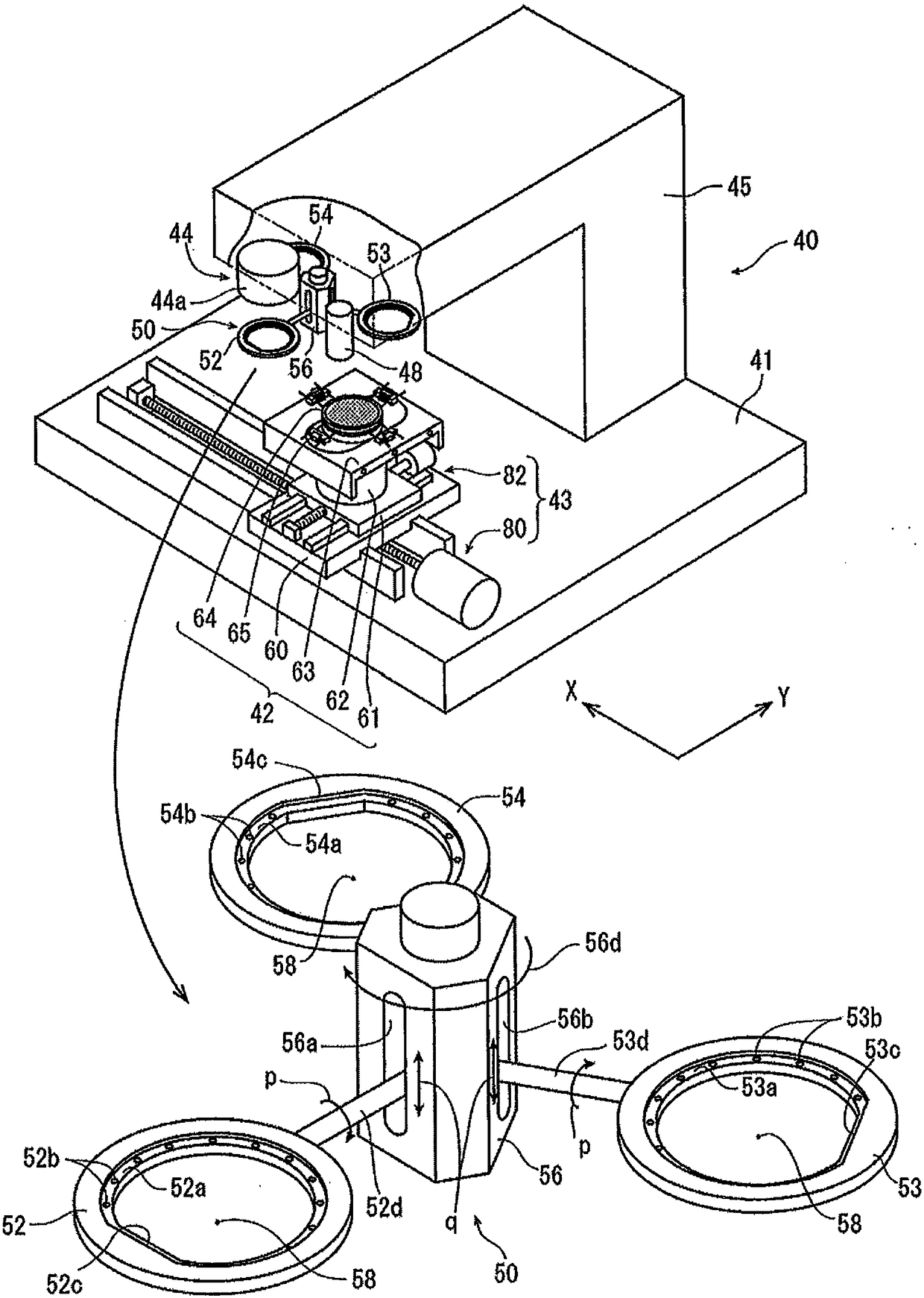
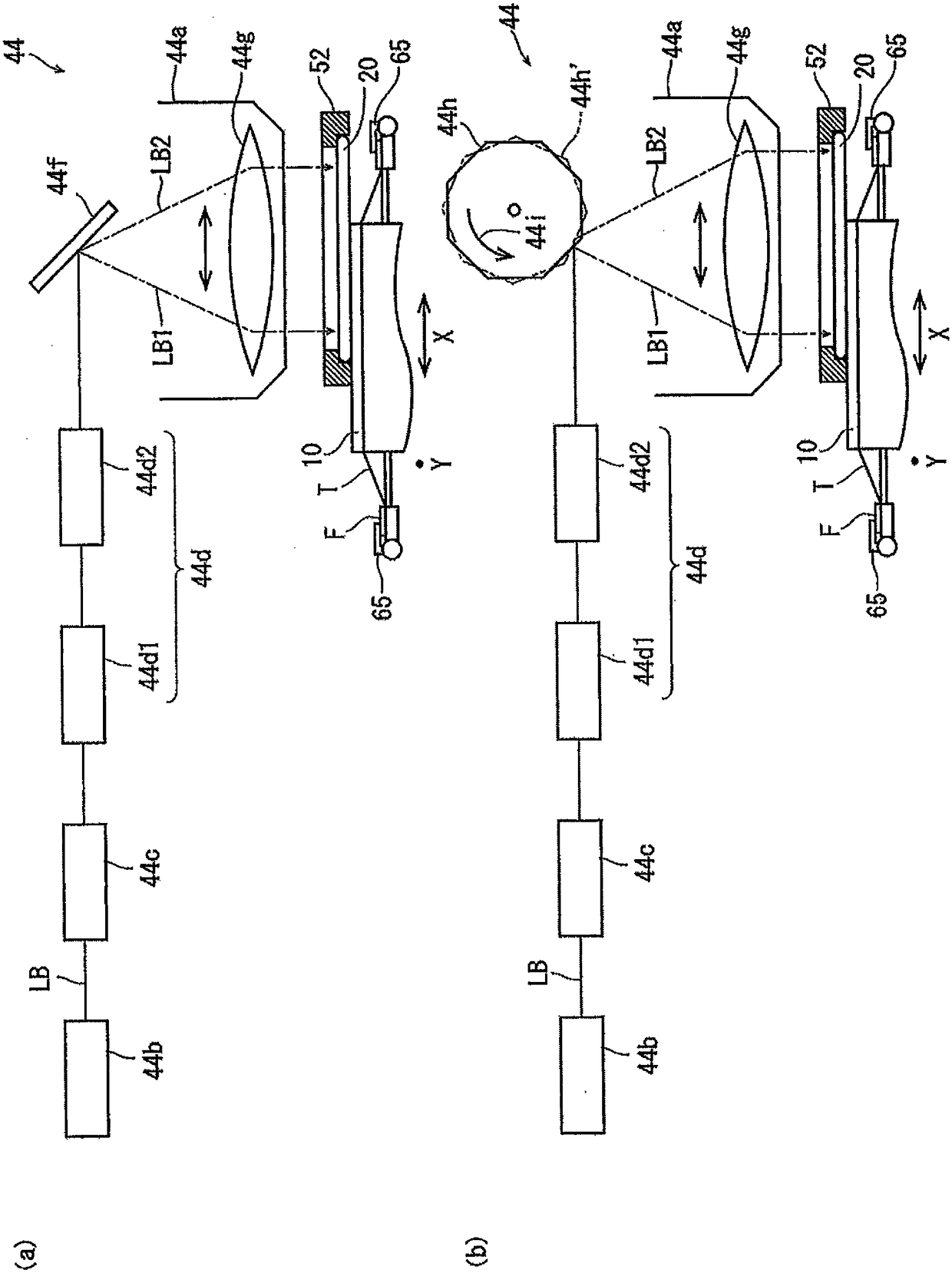
[0027] refer to figure 1 , the die bonder 40 in this embodiment will be described. The die bonding machine 40 shown in the figure has: a base 41; a substrate holding unit 42, which holds a substrate bonded with a device; a moving unit 43, which moves the substrate holding unit 42; and a laser light irradiation unit 44, which irradiates laser light; casing 45, which extends upward from the upper surface of base 41, and then extends substantially horizontally, and houses the laser light irradiation unit 44; and a control unit, which is composed of a computer described later. 40 is configured to control each unit by the control unit. In addition, on the lower surface of the front end portion of the housing 45 extending horizontally, there are provided: a condenser 44a constituting the laser beam irradiation unit 44, which i...


PUM


Abstract

The invention provides a die bonder, which can bond devices such as LEDs, ICs and LSIs to a substrate with high efficiency. The die bonder at least comprises a substrate holding unit (42), a wafer holding unit (50), a facing unit, a device locating unit and a laser irradiation unit. The substrate holding unit has a holding surface which is defined by the X-axis direction and the Y-axis direction and used for holding a substrate which stacks LED layers across stripping layers on the upper surface of an extension substrate (201, 221, 241) for device bonding. The wafer holding unit (50) is used for holding the outer periphery of a wafer (LED wafer 20, 22, 24) with multiple devices arranged on the front surface across the stripping layers. The facing unit makes the front surface of the wafer held by the wafer holding unit face the upper surface of the substrate held by the substrate holding unit. The device locating unit makes the substrate holding unit and the wafer holding unit move in the X-direction and the Y-direction oppositely to locate the devices on the wafer to predetermined positions of the substrate. The laser irradiation unit irradiates laser light from the back surface ofthe wafer to destroy the stripping layers of corresponding devices to bond the devices to the predetermined positions of the substrate.

Description

technical field [0001] The present invention relates to a die bonder for efficiently bonding a plurality of devices to a wiring board. Background technique [0002] For a wafer in which a plurality of LEDs are formed by epitaxial growth on the upper surface of an epitaxial substrate such as a sapphire substrate and a SiC substrate and divided by a planned dividing line, the planned dividing line is cut together with the epitaxial substrate by laser light or the like to generate individual LEDs, wherein , the LED is composed of an epitaxial layer and an electrode, the epitaxial layer is composed of a buffer layer, an N-type semiconductor layer, a light emitting layer and a P-type semiconductor layer, and the electrode is arranged on the N-type semiconductor layer and the P-type semiconductor layer. In addition, the divided red LEDs, green LEDs, and blue LEDs are assembled as modules by a die bonding machine that bonds them to module chips (substrates), and are used, for examp...

Claims


Application Information

Patent Timeline
Patent Type & Authority Applications(China)
IPC IPC(8): H01L21/67H01L33/00
CPCH01L33/0095H01L21/67144H01L21/67092H01L21/67259B23K26/38H01L24/75
Inventor 川合章仁森数洋司
Owner DISCO CORP
Learn More