
System and method for providing egr to engine

A technology of engine and engine load, applied in the direction of engine components, combustion engine, engine control, etc., to achieve the effect of reducing the possibility, reducing the tendency of knocking, and reducing the generation of NOx

Active Publication Date: 2022-05-31
FORD GLOBAL TECH LLC
View PDF5 Cites 0 Cited by
  • Summary
  • Abstract
  • Description
  • Claims
  • Application Information

AI Technical Summary

Problems solved by technology

Retarding the intake valve closing reduces the effective compression ratio of the engine reducing compression heating, but this benefit may be offset by heating the charge being pushed back into the intake via the cylinder walls, cylinder head and heat from the piston to be heated

Method used


Image

  • System and method for providing egr to engine
  • System and method for providing egr to engine
  • System and method for providing egr to engine

Examples


Embodiment Construction

[0013] The following description relates to systems and methods for providing EGR to an engine. In one example, the engine may include

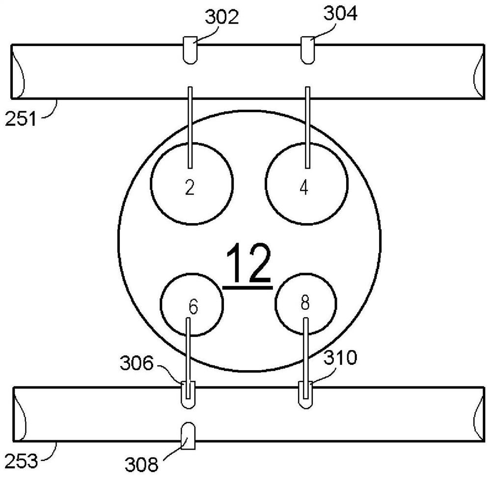
[0014] In the following description, the poppet valve is operable or activated to indicate that it is

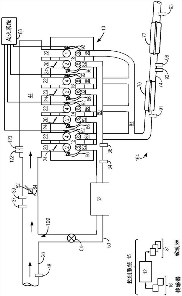
[0015] FIG. 1 shows a schematic diagram of a multi-cylinder internal combustion engine 10 that may be included in a propulsion system of an automobile. launch

[0017] One or more of the intake passages may include a charge motion control valve (CMCV). As shown in Figure 1, the

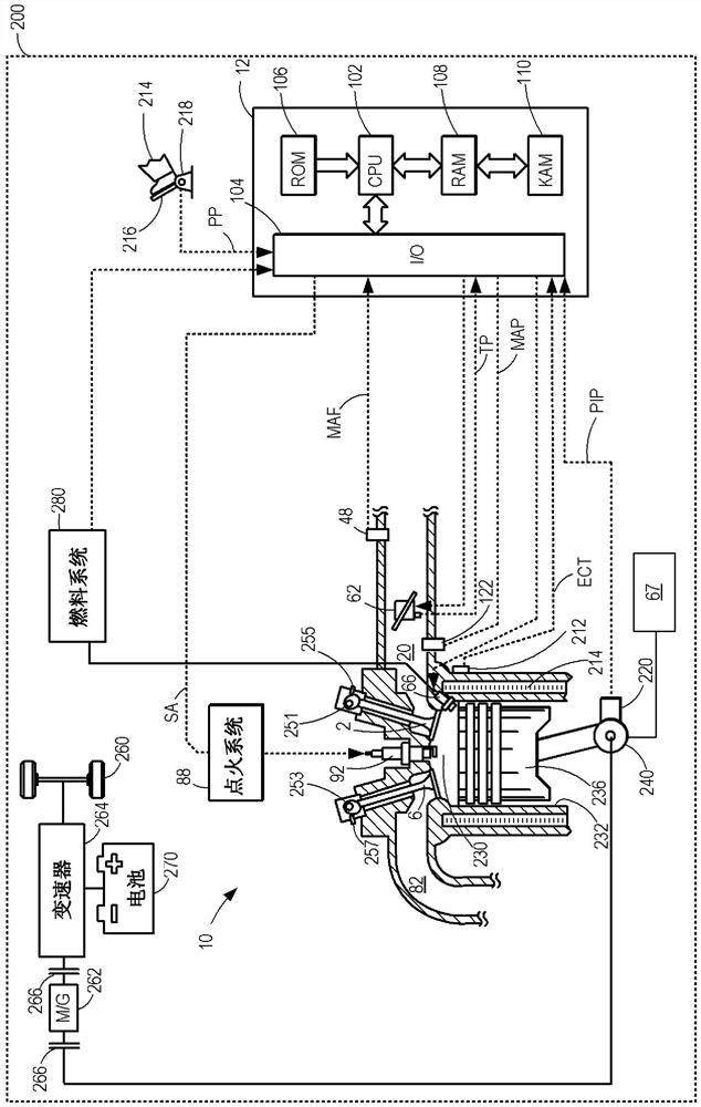
[0018] A high pressure dual stage fuel system, such as the fuel system shown in FIG. 2, may be used to generate fuel at injector 66

[0019] Each exhaust runner may selectively communicate with a cylinder with which each exhaust runner is in fluid communication via an exhaust valve

[0027] In some examples, the engine 10 may be coupled to an electric motor / battery system in a hybrid vehicle (FIG. 2

[0030] Referring now to FIG. 2, which depicts a portion of a single...


PUM


Abstract

The present invention relates to systems and methods for providing EGR to an engine. A method and system for providing exhaust gas recirculation to a naturally aspirated internal combustion engine is provided. In one example, exhaust is recirculated to the engine intake via a dedicated scavenge manifold and scavenged exhaust valve. Because exhaust and fresh air are returned to the engine intake at a pressure greater than atmospheric pressure, exhaust and fresh air that did not participate in combustion can be recirculated to the engine cylinders even at high engine loads.

Description

System and method for providing EGR to an engine technical field The present invention generally relates to a method and system for recirculating exhaust gas to a cylinder of a naturally aspirated internal combustion engine system. Background technique Naturally aspirated internal combustion engines may include exhaust gas recirculation (EGR) to reduce engine pumping work and NOx emissions put. When the intake manifold pressure is lower than the exhaust manifold pressure, exhaust gas may be returned to the intake manifold of the engine. lower intake manifold Pipe pressure provides the motive force to draw exhaust from the exhaust manifold to the intake manifold. Naturally aspirated internal combustion engines can is configured to have an intake valve that closes late in the compression stroke of the cylinder so that a portion of the charge in the cylinder Components (eg, air and fuel) may be pushed back into the engine's intake manifold. By pushing the inflated...

Claims


Application Information

Patent Timeline
Patent Type & Authority Patents(China)
IPC IPC(8): F02D41/00F02M26/23F02D9/08F01L9/20
CPCF02M26/23F02D9/08F02D41/0047F02D41/0065F02D13/0273F02D13/0276F02B25/145F02D13/0242F02D13/0257F01L1/26F01L13/06F02M26/17F01L1/047F02D41/005F01L9/20Y02T10/12Y02T10/40F02D13/0215F02D13/0249F02D41/0077F02D2200/1002
Inventor J·N·尤瑞
Owner FORD GLOBAL TECH LLC
Learn More