Laser range finding system

A laser ranging and laser beam technology, applied in the field of laser ranging, can solve problems such as high cost, complex structure and circuit, and achieve the effects of simplifying the manufacturing process, simple and reliable circuit structure, and reducing manufacturing costs.

Pending Publication Date: 2018-06-22
CHANGZHOU HUADA KEJIE OPTO ELECTRO INSTR
View PDF5 Cites 4 Cited by
  • Summary
  • Abstract
  • Description
  • Claims
  • Application Information

AI Technical Summary

Problems solved by technology

[0005] Both of the above two methods require two light paths inside and outside, so there are problems such as complex structure and circuit, and high cost.

Method used


Image

  • Laser range finding system

Examples


Embodiment Construction

[0021] The advantages of the present invention are further described below in conjunction with the drawings and specific embodiments.

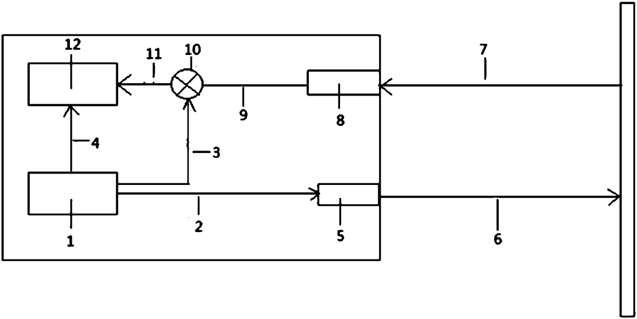
[0022] Refer to figure 1 In the present invention, the laser ranging system includes the following modules:

[0023] -Clock chip

[0024] As the core module of the laser ranging system, it is used to control the entire laser ranging system and output the first main oscillation signal, local oscillation signal and sampling trigger signal respectively. The first main oscillation signal is used to generate the photoelectric mixing signal, the local oscillation signal is used to generate the intermediate frequency signal, and the sampling trigger signal is used to compare with the intermediate frequency signal to calculate the phase difference, and then calculate the length of the measured distance.

[0025] Preferably or alternatively, the initial phases of the sampling trigger signal, the local oscillator signal and the first main oscillator signal are...


PUM


Abstract

The invention provides a laser range finding system. The system comprises a clock chip, a laser emitter, a laser receiver, a frequency mixing device and a microprocessor, wherein the clock chip outputs a local oscillator signal, a first main vibration signal and a sampling trigger signal; the laser emitter is connected to the clock chip, receives the first main vibration signal and emits a first laser beam to a target object under the modulation of the first main vibration signal, and the target object reflects a second laser beam; the laser receiver is arranged on a second laser beam path, receives the second laser beam and generates a second main vibration signal; the frequency mixing device is connected to the clock chip and the laser receiver, and receives and mixes the local oscillator signal and the second main vibration signal so as to generate an intermediate frequency signal; and the microprocessor is connected to the clock chip and the frequency mixing device, receives the intermediate frequency signal and the sampling trigger signal, calculates a phase difference and calculates a distance between the laser emitter and the target object according to the phase difference.By using the above technical scheme, through using the control of the clock chip, an existing laser range finding scheme is simplified, manufacturing cost is saved and product stability is increased.

Description

Technical field [0001] The invention relates to the field of laser ranging, in particular to a laser ranging system. Background technique [0002] Laser rangefinder, as a non-contact measuring instrument, has been widely used in the fields of remote control, precision measurement, engineering construction, safety monitoring and intelligent control. The phase laser rangefinder has high accuracy, low power and so convenient. Features, suitable for civilian use, has a larger market and application prospects. The phase method is used to measure the phase displacement of the modulated light wave after propagating through the air, so as to find the distance traveled by the light wave. [0003] Traditional phase laser rangefinders generally adopt single-shot dual-receiving or dual-shot single-receiving mode. In the single-shot dual-receiving mode, the laser transmitter generates photoelectric mixing by electric modulation signals on the mixing device of the inner optical path and the out...

Claims


Application Information

Patent Timeline
Patent Type & Authority Applications(China)
IPC IPC(8): G01S17/08G01S7/481
CPCG01S7/4811G01S17/08
Inventor 张瓯王建勇
Owner CHANGZHOU HUADA KEJIE OPTO ELECTRO INSTR
Why Eureka
Try Eureka