Metal pipe fitting forming device and method based on through-flow mode
A technology for metal pipe fittings and pipe fittings, which is applied in the field of metal pipe fitting forming devices based on flow mode, can solve the problems of difficulty in forming small diameter and special-shaped pipe fittings, stress damage, coil temperature rise, etc., so as to avoid the problems of temperature rise and stress damage. , the effect of improving production efficiency, saving design and production costs
- Summary
- Abstract
- Description
- Claims
- Application Information
AI Technical Summary
Problems solved by technology
Method used
Image
Examples
no. 1 example
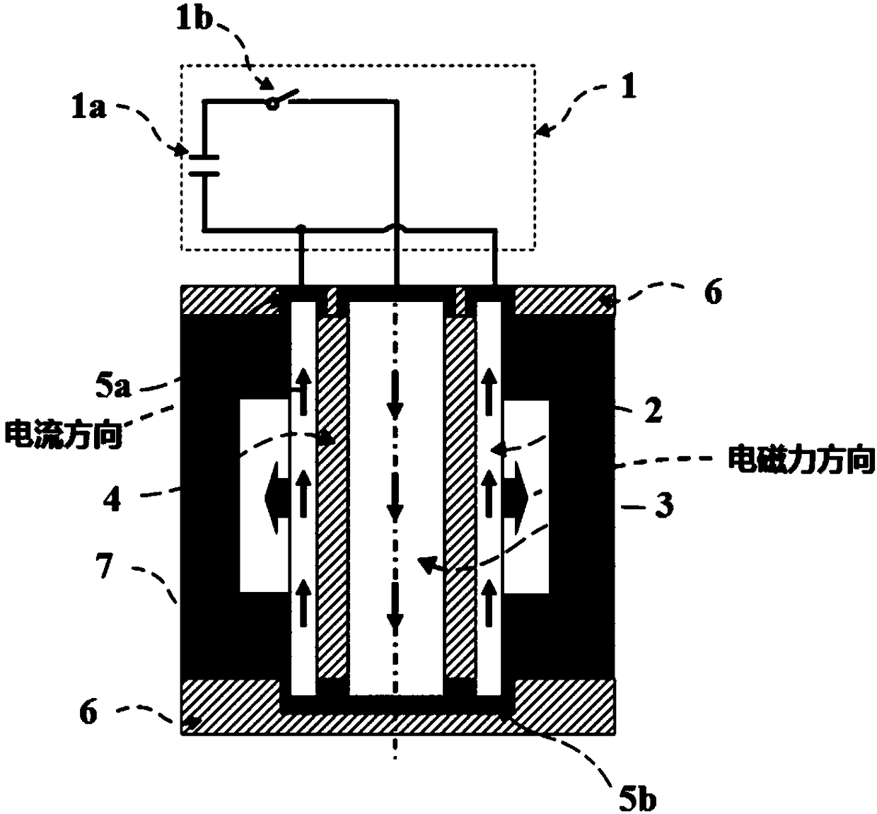
[0039] figure 1 An electromagnetic forming device for a small-diameter metal pipe fitting based on a through-flow mode provided by the present invention. Among them, the power supply system 1 is composed of a pulse capacitor 1a and a switch 1b. In the forming system, the forming pipe fitting 2 is an aluminum alloy seamless pipe with an inner diameter of 20 mm and a wall thickness of 2 mm. An insulating mold 7 with a forming groove is placed outside the forming pipe fitting to control the bulging shape of the pipe fitting. A solid copper rod with a radius of 8mm is placed concentrically inside the shaped pipe 2 as a shaped driving rod 3, and an epoxy insulating sleeve 4 with a wall thickness of 2mm is used to isolate the two to avoid short circuit. The connecting electrodes 5a are closely attached to the outer sides of the upper ports of the forming pipe and the forming driving rod respectively and connected to the positive and negative poles of the power supply system. The tw...
no. 2 example
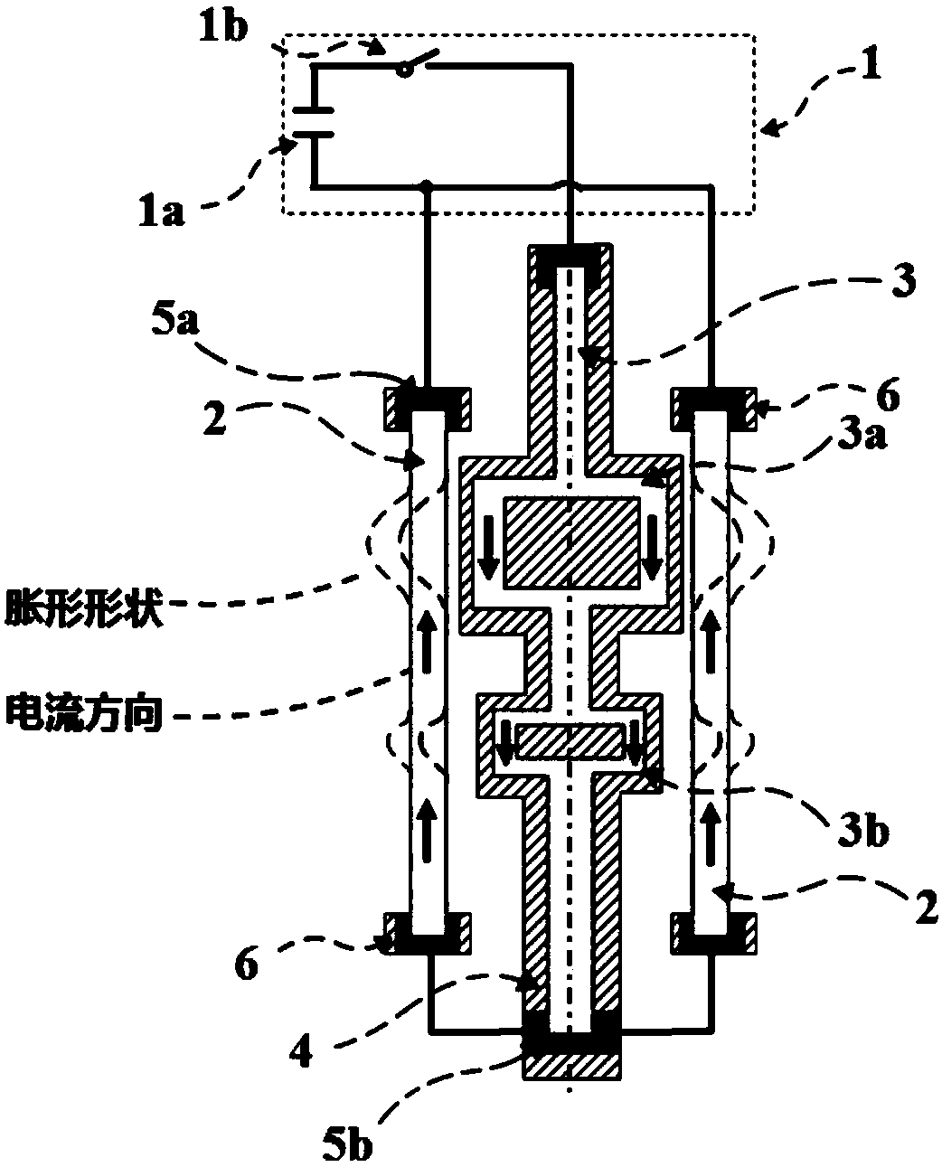
[0043] figure 2 The electromagnetic forming device for special-shaped metal pipe fittings based on the flow mode provided by the present invention is especially suitable for forming metal pipe fittings without a mold. Among them, the power supply system 1 is composed of a pulse capacitor 1a and a switch 1b. In the forming system, the forming pipe fitting 2 is an aluminum alloy seamless pipe with an inner diameter of 20 mm and a wall thickness of 2 mm. Compared with the first embodiment, the size and shape of the shaped drive rod 3 are changed in this embodiment, wherein the radius is reduced to 2 mm to increase the current density in the shaped drive rod. In addition, a partial area of the forming driving rod 3 is bent to form the first protrusion 3 a and the second protrusion 3 b, while the main part is still placed concentrically with the forming pipe 2 . The shaped driving rod 3 is wrapped by an epoxy insulating sleeve 4 to ensure a sufficiently high mechanical strengt...
no. 3 example
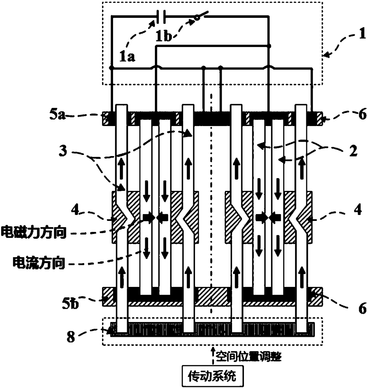
[0046] image 3 An electromagnetic forming device for welding metal pipe fittings based on the through-flow mode provided by the present invention. Among them, the power supply system 1 is composed of a pulse capacitor 1a and a switch 1b. In the forming system, the forming pipe fitting 2 is two aluminum alloy seamless pipes placed concentrically, the inner diameter and wall thickness of the inner pipe fitting are 20mm and 2mm respectively, and the inner diameter and wall thickness of the outer pipe fitting are 23mm and 2mm respectively. In this embodiment, two shaped driving rods 3 are used, the convex parts of which are pointed to increase the current density, and the convex parts of the two shaped driving rods 3 are on the same horizontal plane. The insulating sleeve 4 is arranged on the inner and outer sides of the protruding part of the forming driving rod 3 to ensure that the protruding part of the driving rod is not deformed during the forming process of the pipe. The ...
PUM
| Property | Measurement | Unit |
|---|---|---|
| thickness | aaaaa | aaaaa |
Abstract
Description
Claims
Application Information
 - R&D
- Intellectual Property
- Life Sciences
- Materials
- Tech Scout
- Unparalleled Data Quality
- Higher Quality Content
- 60% Fewer Hallucinations
Browse by: Latest US Patents, China's latest patents, Technical Efficacy Thesaurus, Application Domain, Technology Topic, Popular Technical Reports.
© 2025 PatSnap. All rights reserved.Legal|Privacy policy|Modern Slavery Act Transparency Statement|Sitemap|About US| Contact US: help@patsnap.com


