Hydraulic pressure engine based on reversing valve

A reversing valve and engine technology, applied in the field of water energy power machinery, can solve the problems of low water energy utilization rate and large space occupation, and achieve the effects of simple structure, stable and reliable power output, and high energy conversion efficiency

Active Publication Date: 2018-06-19
彭秀龙
View PDF5 Cites 2 Cited by
  • Summary
  • Abstract
  • Description
  • Claims
  • Application Information

AI Technical Summary

Problems solved by technology

It solves the problem that the existing hydropower generation / power conversion device occupies a large space and the utilization rate of water energy is low

Method used


Image

  • Hydraulic pressure engine based on reversing valve
  • Hydraulic pressure engine based on reversing valve
  • Hydraulic pressure engine based on reversing valve

Examples


Embodiment 1

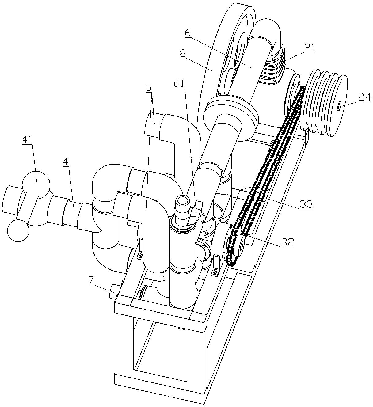
[0033] Such as figure 1 , 2 , 5, 6, 7, and 9, the hydraulic engine based on the reversing valve includes a reversing valve, an engine, a transmission assembly, a water inlet pipe 4, a drain pipe 5, a communication pipe 6 and a slag discharge pipe 7.

[0034] The reversing valve includes a casing 11 and a valve core 12 . The shell 11 is provided with a water inlet 111 , a water outlet A112 , a water outlet B113 and a water return port 114 . The valve core 12 is sealed and rotatably installed in the inner cavity of the casing 11, and its two ends protrude from the outside of the casing 11, and a water-permeable hole 121 is arranged on it, which realizes the opening or closing of the reversing valve through rotation. When the reversing valve is in the water inlet state, the permeable hole 121 of the spool 12 is rotated to communicate with the water inlet 111 and the water outlet A112 of the casing 11, and the inner cavity of the spool 12 is only connected with the water inlet 1...

Embodiment 2

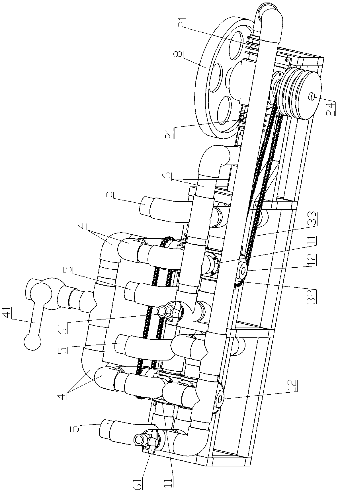
[0052] Such as image 3 , 4 , 5, 6, 8, and 10, compared with Embodiment 1, the present embodiment differs only in that the number of reversing valves is two, and the spools 12 of the two reversing valves are connected by a chain transmission pair, correspondingly Yes, there are two cylinder blocks 21, pistons 22, and connecting rods 23 of the engine. Compared with Embodiment 1, this embodiment has the advantage that the output of the crankshaft 24 is more stable.

[0053] Working principle of embodiment 2: the working principle of this embodiment is the same as that of embodiment 1, the only difference is that the working states of the two reversing valves are always opposite, that is, when one reversing valve is in the state of water intake, the other reversing valve The directional valve must be in the drain state.


PUM


Abstract

The invention discloses a hydraulic pressure engine based on a reversing valve. The hydraulic pressure engine comprises the reversing valve, an engine body, a transmission assembly, a water inlet pipe, a water draining pipe and a communicating pipe; the reversing valve comprises a shell and a valve core; the valve core is rotatably mounted in an inner cavity of the shell in a sealing mode, and thevalve core makes the reversing valve switch between the two states of water inlet and water draining through rotating; the engine body comprises a cylinder body, a piston, a connecting rod and a crankshaft; the transmission assembly is used for transmitting power from the crankshaft of the engine body to the valve core of the reversing valve; the water inlet pipe communicates with a water inlet of the reversing valve; the water draining pipe communicates with a water outlet B of the reversing valve; and one end of the communicating pipe communicates with a water outlet A and a water return port of the reversing valve, and the other end of the communicating pipe communicates with a water port of the engine body. According to the hydraulic pressure engine based on the reversing valve, kinetic energy of water is converted into mechanical energy, the structure of the hydraulic engine is simple and small, power output is stable and reliable, the energy conversion efficiency is high, and the hydraulic engine can be used for being connected to other power devices for doing work.

Description

technical field [0001] The invention relates to the field of hydraulic power machinery, in particular to a hydraulic engine based on a reversing valve. Background technique [0002] Water energy has been widely used as a clean energy source. Most of the utilization of water energy in the prior art is to convert water energy into electrical energy. Hydropower generation is the most common way of utilizing water energy in its application. , cooperate with the water wheel generator to generate electricity, that is, use the potential energy of water to convert the mechanical energy of the water wheel, and then use the mechanical energy to drive the generator to obtain electricity. Scientists take advantage of the natural conditions of the water level drop to effectively use fluid engineering and mechanical physics, etc., and carefully match them to achieve the highest power generation, so that people can use cheap and pollution-free electricity. It can be seen that the core com...

Claims


Application Information

Patent Timeline
Patent Type & Authority Applications(China)
IPC IPC(8): F03C1/02F03C1/08
CPCF03C1/002F03C1/02F03C1/08
Inventor 彭秀龙
Owner 彭秀龙
Why Eureka
Try Eureka