Tunnel lighting control system based on self-powered carrier wireless dual-mode communication

A technology of tunnel lighting control and self-power supply, which is applied in the direction of lighting devices, energy-saving control technology, electric light source, etc., and can solve the problems of not realizing carrier wireless dual-mode communication, power supply system not being able to realize self-power supply, and not using natural energy for power supply, etc. Achieve the effect of eliminating manual inspection, reducing power consumption, and accurate operation

Active Publication Date: 2019-03-19
CHANGAN UNIV
View PDF7 Cites 0 Cited by
  • Summary
  • Abstract
  • Description
  • Claims
  • Application Information

AI Technical Summary

Problems solved by technology

However, there are only wired carriers, the communication speed is slow, and the reliability is poor. Moreover, the geographical location of the tunnels is mostly built in mountainous areas or high-altitude mountainous areas, rich in natural resources, and does not use natural energy for power supply.
[0003] Chinese patent CN201310028843.8 discloses a tunnel lighting plus security system. The system includes a control center, a lighting system, a signal lamp and an indicating alarm; Electric energy, but the power supply system of this system cannot realize self-power supply and does not utilize natural resources; Patent CN201110175994.7 discloses a LED lighting control system for tunnel traffic. The best lighting effect and the best energy-saving effect, but it does not realize the dual-mode communication of carrier wireless

Method used


Image

  • Tunnel lighting control system based on self-powered carrier wireless dual-mode communication
  • Tunnel lighting control system based on self-powered carrier wireless dual-mode communication
  • Tunnel lighting control system based on self-powered carrier wireless dual-mode communication

Examples


Embodiment 1

[0027] This embodiment mainly introduces the basic composition of a self-powered tunnel lighting system.

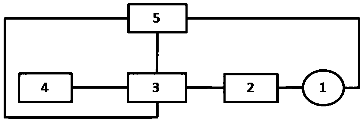
[0028] Such as figure 1 Shown is a tunnel lighting control system based on self-powered carrier wireless dual-mode communication, including a lamp 1, a terminal controller 2, a centralized controller 3, a host computer 4, and a water flow pipe TEG module 5; among them, the lamp and the terminal There are multiple controllers, the lamps are connected to the terminal controller, the terminal controller is connected to the centralized controller, and the centralized controller is connected to the host computer; a terminal controller is installed on the lamp holder of each lighting lamp to be responsible for the switch control of the lamps , and feed back the operating parameters of the lamps to the centralized controller at the same time; the centralized controller collects real-time data of traffic flow and brightness values ​​inside and outside the tunnel, and completes th...

Embodiment 2

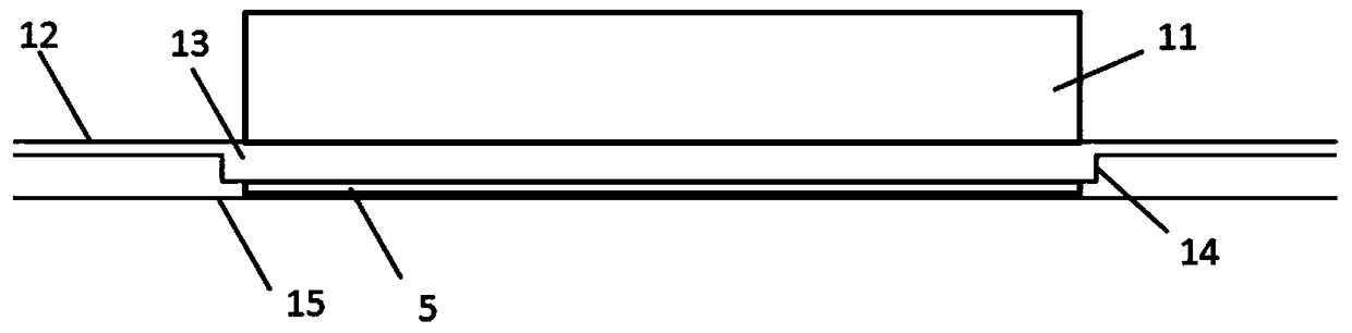
[0030] This embodiment is carried out on the basis of the first embodiment above, and mainly introduces the schematic diagram of the side section of the tunnel where the water flow tube TEG module is embedded as a power supply system, and the principle and technical solution of the self-power supply of the water flow tube TEG module.

[0031] The embedding method of the water flow pipe TEG module inside the tunnel is as follows: figure 2 As shown, 11 represents a section of tunnel, the subgrade 13 is buried directly below the tunnel pavement 12, the heat collecting pipe 14 is buried under the subgrade 13, 15 is the underground water pipeline under the subgrade, and 5 is the water flow pipe TEG module embedded between the heat collecting pipe 14 and the groundwater Between pipes 15.

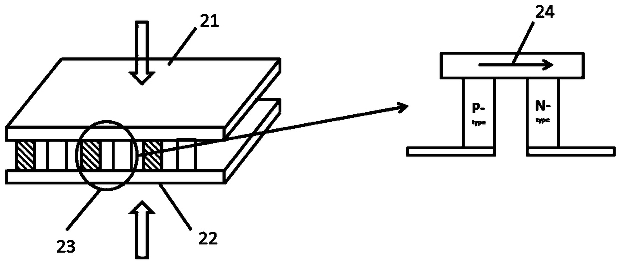
[0032] Such as image 3 Shown is the internal structure of the water flow tube TEG module 5, which is obtained by connecting many pairs of PN junctions 23 in series, and uses the Seebeck effect ...

Embodiment 3

[0038] This embodiment is carried out on the basis of the foregoing embodiment 1 or 2, and mainly introduces the structure of the lighting control system and their technical solutions.

[0039] Such as Figure 4 It is a schematic diagram of the structural connection of the lighting control system. The water flow pipe TEG module 5 provides the electric energy required by the entire system; the vehicle detector 37 and the light intensity detector 38 of the data acquisition module of the centralized controller send the collected data to the STM32 of the control module In the chip AT89C51 processor 34 of model, then information is transmitted in the upper computer 4 by carrier wireless transceiver circuit 32 and coupling circuit 31, in this process, use LME2981 chip 33 to realize dual-mode communication; Upper computer 4 can send to each relay The control circuit 36 ​​sends instructions to control the switch of the lamp 1. The upper computer also transmits information through the ...


PUM


Abstract

The invention provides a self-power-supply-based carrier wave wireless dual mode communication tunnel illumination control system. The self-power-supply-based carrier wave wireless dual mode communication tunnel illumination control system includes lamps, terminal controllers, an integrated controller, a host computer and a water flow pipe TEG (Thermoelectric Generation) module, wherein the self-power-supply-based carrier wave wireless dual mode communication tunnel illumination control system has a plurality of lamps and terminal controllers; one terminal controller is arranged on each lamp;a switch for controlling the lamps feeds back the corresponding data to the integrated controller; the integrated controller feeds back the acquired data to the host computer by acquiring the vehicleflow data in the tunnel and the internal and external luminance of the entrance of the tunnel, and issues a command of the host computer to the terminal controllers, so as to complete setting of the working state of each lamp; and the water flow pipe TEG module is the power supply of the whole system. The self-power-supply-based carrier wave wireless dual mode communication tunnel illumination control system can realize real-time monitoring, control and management of lamps in the tunnel, can record and analyze the operating data of each equipment so as to guarantee efficient and accurate operation of the lamps in the tunnel and safe operation of the tunnel, and has preferable application prospect and market value.

Description

technical field [0001] The invention relates to the field of lighting control, in particular to a self-powered tunnel lighting control system. Background technique [0002] In the prior art, the tunnel lighting control system communicates through the power line carrier, and the English abbreviation is PLC (Power Line Communication), which is a general term for communication methods that use the power line carrier to realize information transmission. This technology loads the high-frequency signal carrying information onto the power line, uses the power line for data transmission, separates the high-frequency signal from the power line through a dedicated power line modem, and transmits it to the terminal equipment. However, there are only wired carriers, the communication speed is slow, and the reliability is poor. Moreover, the tunnels are mostly built in mountainous or high-altitude mountainous areas, rich in natural resources, and do not use natural energy for power suppl...

Claims


Application Information

Patent Timeline
Patent Type & Authority Patents(China)
IPC IPC(8): H05B37/02
CPCH05B47/10H05B47/19Y02B20/40
Inventor 肖剑耿洪扬董威邵强张雪璠金正杰陶徐文李翔杜亚伟
Owner CHANGAN UNIV
Why Eureka
Try Eureka