Microwave combiner

A microwave combiner and path technology, applied in waveguide-type devices, circuits, electrical components, etc., can solve the problems of low isolation, low integration, 3dB loss, etc., to reduce filters and 3dB combiners, The effect of improving integration

Active Publication Date: 2018-06-15
SHANGHAI HUAWEI TECH CO LTD
View PDF6 Cites 4 Cited by
  • Summary
  • Abstract
  • Description
  • Claims
  • Application Information

AI Technical Summary

Problems solved by technology

In the existing technology, such as figure 1 As shown, the existing combining schemes generally use 3dB bridges for combining circuits, but when using 3dB bridges for co-frequency combining, the isolation is low, there is at least 3dB loss, and the constituted system is complex and the integration level is not high.

Method used


Image

  • Microwave combiner
  • Microwave combiner
  • Microwave combiner

Examples


Embodiment Construction

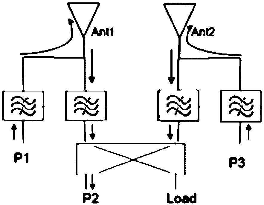
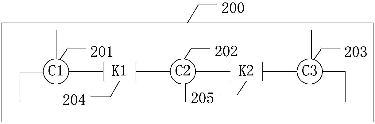
[0025] The embodiment of the present application provides a microwave combiner, which is used in a new radio frequency front-end subsystem. Compared with the prior art, the number of filters and 3dB combiners can be reduced, and the integration degree can be improved.

[0026] The terms "first", "second", "third", "fourth", etc. (if any) in the specification and claims of the present application and the above drawings are used to distinguish similar objects, and not necessarily Used to describe a specific sequence or sequence. It is to be understood that the terms so used are interchangeable under appropriate circumstances such that the embodiments described herein can be practiced in sequences other than those illustrated or described herein. Furthermore, the terms "comprising" and "having", as well as any variations thereof, are intended to cover a non-exclusive inclusion, for example, a process, method, system, product or device comprising a sequence of steps or elements is...


PUM


Abstract

The embodiments of the present invention disclose a microwave combiner. The microwave combiner is used for a new radio frequency front-end subsystem. Compared with the prior art, the microwave combiner can assist in reducing filters and 3dB combiners and improving integration. The microwave combiner includes a first common cavity, a second common cavity, a third common cavity, a first impedance converter and a second impedance converter; the first interface of the first common cavity is connected with a first signal input interface; the second interface of the first common cavity is connectedwith a first antenna interface; the third interface of the first common cavity is connected with one end of the first impedance converter; the first interface of the second common cavity is connectedwith the other end of the first impedance converter; the second interface of the second common cavity is connected with a signal output interface; the third interface of the second common cavity is connected with one end of the second impedance converter; the first interface of the third common cavity is connected with the other end of the second impedance converter; the second interface of the third common cavity is connected with a second antenna interface; and the third interface of the third common cavity is connected with a second signal input interface.

Description

technical field [0001] The present application relates to the field of microwave filter combining, in particular to a microwave combiner. Background technique [0002] With the increasing demand for base station miniaturization, the filter, as a key component in the base station module, needs to further increase the integration level. [0003] With the rapid development of the filter industry, the requirements for filter indicators are also constantly increasing. This is mainly reflected in the fact that multi-channel products share one antenna interface, high out-of-band rejection and good in-band insertion loss. small volume. In the existing technology, such as figure 1 As shown, the existing combining schemes generally use 3dB bridges for combining circuits, but when using 3dB bridges for co-frequency combining, the isolation is low, there is at least 3dB loss, and the constituted system is complex and the integration level is not high. . Contents of the invention ...

Claims


Application Information

Patent Timeline
Patent Type & Authority Applications(China)
IPC IPC(8): H01P1/213
Inventor 袁本贵宋炎林
Owner SHANGHAI HUAWEI TECH CO LTD
Why Eureka
Try Eureka