Anti-seismic bridge support
A bridge bearing and chute technology, used in bridges, bridge construction, bridge parts, etc., can solve the problems of inconsistent vibration frequency, structural damage of bridges, and inability to protect piers, so as to increase the difficulty, strengthen the protection ability, and make it difficult to side shift effect
- Summary
- Abstract
- Description
- Claims
- Application Information
AI Technical Summary
Problems solved by technology
Method used
Image
Examples
Embodiment 1
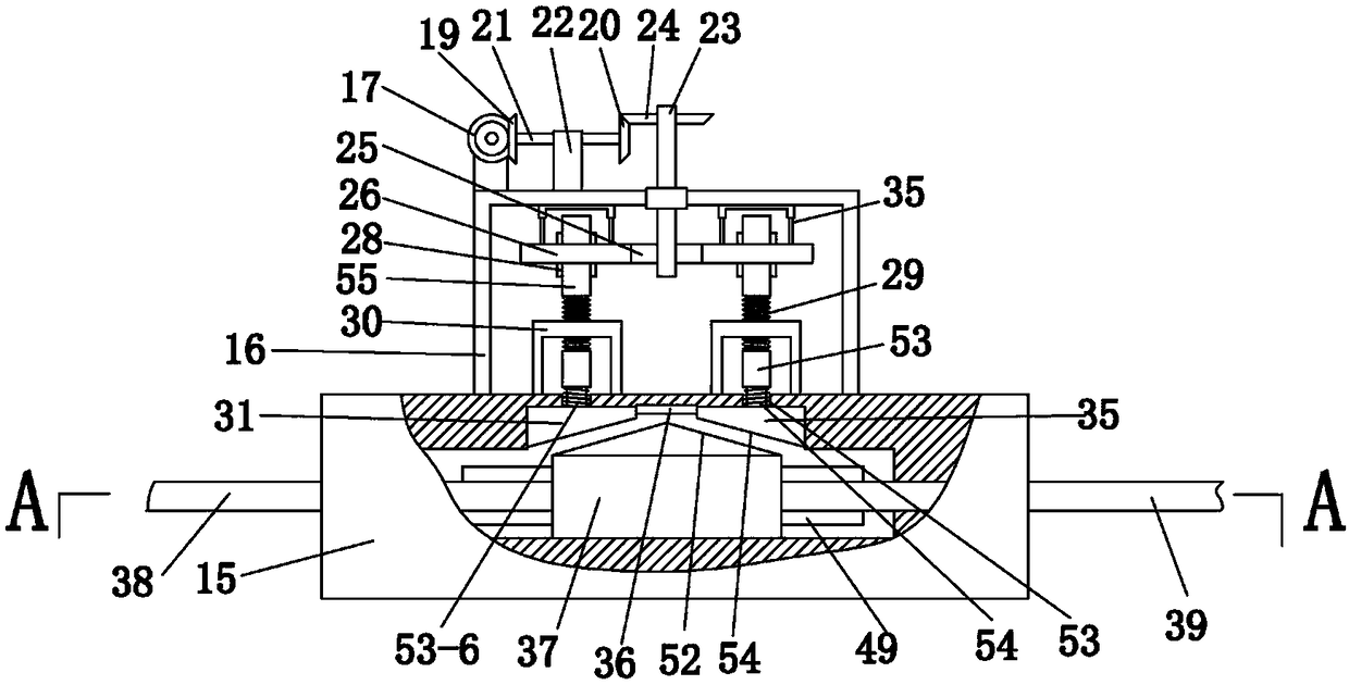
[0035] Embodiment 1, please combine the attached figure 1 , 2 , can clearly see the position of the present invention in the bridge, the present invention includes two cams 1, the cams 1 are respectively rotatably connected in the grooves 3 on both sides of the abutment 2, in the initial state, the distance of the cam 1 rotates The farthest point is placed directly below, and the groove 3 where the cam 1 is installed should not be too large, so as not to affect the overall seismic strength of the abutment 2. The lower part of the front end of the cam 1 is rotatably connected with a drive rod 4, and the drive rod 4 is separately One end is tilted outward and hinged below the main beam 5. The horizontal movement of the main beam 5 can drive the cam 1 to rotate through the driving rod 4. The upper part of the groove 3 is connected with the first chute 32 that penetrates the abutment 2 upwards. A retaining rod 6 is placed above the cam 1, and the retaining rod 6 passes through th...
Embodiment 2
[0038] Embodiment 2, on the basis of Embodiment 1, please combine the attached figure 1 , the top of the cam 1 has two symmetrical protrusions along the radial direction of the cam 1 respectively, so that the cam 1 can push up the blocking rod 6 when it rotates clockwise or counterclockwise. The cam 1 is left-right symmetrical, so that the clockwise and counterclockwise motions of the cam give the movement trend of the stop rod to be consistent.
Embodiment 3
[0039] Example 3, on the basis of Example 1, please combine Figure 5 The telescopic universal joint 18 is that the universal joint 18 includes a second telescopic rod, and the second telescopic rod is slidably connected to the second cylinder 18-4 by the second cylinder 18-4. 4 inside the second movable rod 18-3, the second cylindrical body 18-4 has an axial third chute 18-7 communicating with its inner cavity, and the second movable rod 18-3 is fixed on There is a first sliding block 18-8 axially slidingly fitted in the third chute 18-7, and the free ends of the second movable rod 18-3 and the second cylindrical body 18-4 are respectively fixed with universal joints 18 -2, wherein one universal joint 18-2 is connected on the rotating shaft 18-6, and another universal joint 18-2 is connected on the transmission shaft 18-1. The structure that the third chute 18-7 and the first sliding block 18-8 cooperate with each other is set in the second telescopic rod, so that the second...
PUM
 Abstract
Description
Claims
Application Information
 - R&D
- Intellectual Property
- Life Sciences
- Materials
- Tech Scout
- Unparalleled Data Quality
- Higher Quality Content
- 60% Fewer Hallucinations
Browse by: Latest US Patents, China's latest patents, Technical Efficacy Thesaurus, Application Domain, Technology Topic, Popular Technical Reports.
© 2025 PatSnap. All rights reserved.Legal|Privacy policy|Modern Slavery Act Transparency Statement|Sitemap|About US| Contact US: help@patsnap.com


