Ultrasonic cutting robot

A cutting robot and ultrasonic technology, applied in the direction of manipulators, program-controlled manipulators, metal processing machinery parts, etc., can solve the problems of large machine tool area, complex machine tool structure, and large machine tool quality, so as to achieve fast cutting speed and reduce equipment occupation. The effect of floor area and high automation level

Pending Publication Date: 2018-06-15
杭州辉昂科技有限公司
View PDF0 Cites 5 Cited by
  • Summary
  • Abstract
  • Description
  • Claims
  • Application Information

AI Technical Summary

Problems solved by technology

[0003] (1) The structure of the machine tool is complex and the production cost is high;
[0004] (2) For advanced composite parts with complex shapes, it is often difficult to process;
[0005] (3) The machine tool occupies a large area;
[0006] (4) The machine tool is heavy and heavy

Method used


Image

  • Ultrasonic cutting robot
  • Ultrasonic cutting robot
  • Ultrasonic cutting robot

Examples


Embodiment Construction

[0036] The present invention will be described in further detail below in conjunction with the accompanying drawings.

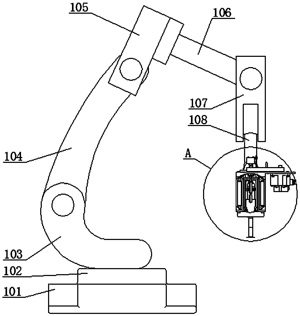
[0037] An ultrasonic cutting robot includes a robot mechanism and an ultrasonic spindle mechanism; the ultrasonic spindle mechanism is installed at the wrist end of the robot mechanism, and the robot mechanism is used to adjust the position and direction of the ultrasonic mechanism.

[0038] The robot mechanism includes a rotating base 102 , a pitching arm 103 , a pitching rear arm 104 , a pitching forearm 105 , a rotating forearm 106 , a pitching wrist 107 , a first support 108 and a second support 109 .

[0039] The bottom of the pitch boom 103 is rotatably mounted on the slewing base 102 . A control device 101 is arranged on the rotating base 102 . A steering gear is arranged between the pitching arm 103 and the rotating base 102 , and the rotation shaft of the steering gear is vertically arranged and passed through the pitching arm 103 and the rotating bas...


PUM


Abstract

The invention discloses a ultrasonic cutting robot, and belongs to the technical field of cutting devices. The ultrasonic cutting robot comprises a robot mechanism and a ultrasonic cutting main shaftmechanism; the ultrasonic cutting main shaft mechanism is mounted at the tail end of the robot mechanism; the robot mechanism adjusts the position and the direction of the ultrasonic cutting main shaft mechanism; and the ultrasonic cutting main shaft mechanism comprises a servo motor, a synchronous belt, a ultrasonic main shaft, an upper contact, a lower contact, a transducer and an amplitude change rod. A robot technology, a numerical control technology, a ultrasonic vibration machining technology and a composite material machining process are applied to the composite material cutting industry to replace five-axis and six-axis linkage numerical control machine tools for composite material machining so as to meet composite material complex shape cutting, milling and punching.

Description

technical field [0001] The invention belongs to the technical field of cutting devices, and in particular relates to an ultrasonic cutting robot. Background technique [0002] In today's life, composite materials are widely used in social life, but advanced composite material processing has become a difficult problem in the scientific community. Generally, six-axis gantry ultrasonic cutting machine tools are used in industry, but gantry cutting machine tools have the following problems: [0003] (1) The structure of the machine tool is complex and the production cost is high; [0004] (2) For advanced composite parts with complex shapes, it is often difficult to process; [0005] (3) The machine tool occupies a large area; [0006] (4) The machine tool is heavy and heavy. [0007] At this stage, robot processing technology and ultrasonic cutting technology have been widely used in industrial production and manufacturing. Robot technology and ultrasonic cutting technology ...

Claims


Application Information

Patent Timeline
Patent Type & Authority Applications(China)
IPC IPC(8): B23P23/02B23B19/02B25J9/00B23D79/00
CPCB23P23/02B23D79/00B23Q1/70B25J9/00B25J9/0009
Inventor 张云电严明康凯张宇
Owner 杭州辉昂科技有限公司
Why Eureka
Try Eureka