
Cutting device for automobile shaft parts

A technology for cutting devices and automobile shafts, applied in positioning devices, driving devices, metal processing machinery parts, etc., can solve the problems of inaccurate cutting accuracy and inconvenient use, and achieve the effect of improving strength

Inactive Publication Date: 2018-06-15
胡仟惠尹
View PDF0 Cites 3 Cited by
  • Summary
  • Abstract
  • Description
  • Claims
  • Application Information

AI Technical Summary

Problems solved by technology

[0002] When making or repairing automobile shaft parts, cutting machines are needed for production and processing. At present, most of the existing auto parts cutting machines are still in the manual operation stage, and most of the cutting machines are in the form of machine tools and fixed on the On the bottom surface or the workbench, the shaft to be cut needs to be fixed on the cutting machine, which has great limitations on the cutting of the shaft. When the shaft to be cut is far away from the cutting workbench and not in the cutting factory , People often use hand-held cutting machines to cut shafts, the cutting accuracy is not accurate, and it is inconvenient to use. There is an urgent need for a device that can be fixed on the shaft and cut stably. For this reason, we propose a car shaft piece cutting device

Method used


Image

  • Cutting device for automobile shaft parts
  • Cutting device for automobile shaft parts
  • Cutting device for automobile shaft parts

Examples


Embodiment Construction

[0025] The following will clearly and completely describe the technical solutions in the embodiments of the present invention with reference to the accompanying drawings in the embodiments of the present invention. Obviously, the described embodiments are only some, not all, embodiments of the present invention. Based on the embodiments of the present invention, all other embodiments obtained by persons of ordinary skill in the art without making creative efforts belong to the protection scope of the present invention.

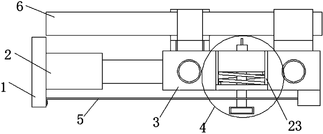
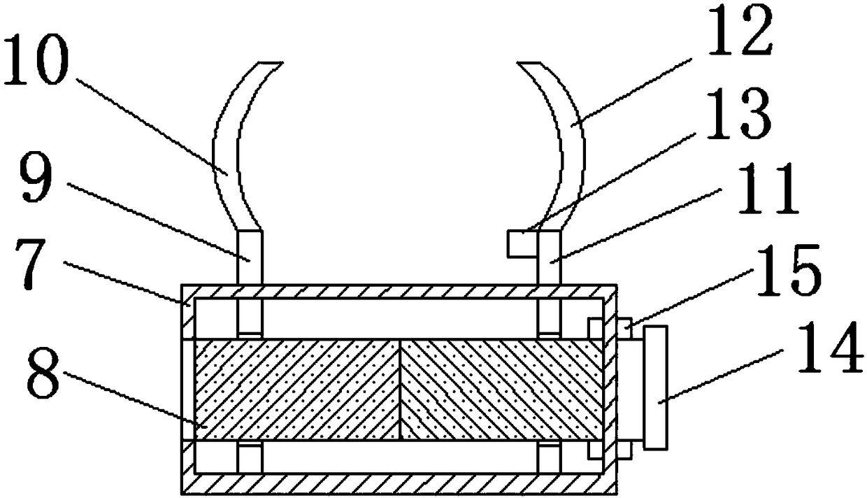
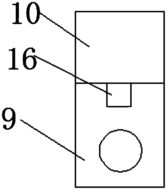
[0026] see Figure 1-7 , the present invention provides a technical solution: a cutting device for automobile shaft parts, including a base plate 1, a hydraulic cylinder 2, a clamping mechanism 3, a cutting mechanism 4 and a measuring mechanism 5, and the hydraulic cylinder 2 is fixed on a part of the base plate 1 side, the output shaft end of the hydraulic cylinder 2 is fixedly connected to the clamping mechanism 3, the side of the clamping mechanism 3 away f...


PUM


Abstract

The invention discloses a cutting device for automobile shaft parts. The cutting device for automobile shaft parts comprises a base plate, a hydraulic cylinder, clamping mechanisms, a cutting mechanism and a measuring mechanism. The hydraulic cylinder is fixed to one side of the base plate. The end, with the output shaft, of the hydraulic cylinder is fixedly connected with one clamping mechanism.The cutting mechanism is arranged on the sides, away from the hydraulic cylinder, of the clamping mechanisms. The clamping mechanisms are arranged on both the two sides of the cutting mechanism. The bottom end of the side face, facing the cutting mechanism, of one clamping mechanism and the bottom end of the side face, facing the cutting mechanism, of the other clamping mechanism are fixedly connected through a connecting plate. A shaft part is clamped between the upper parts of the two clamping mechanisms. The measuring mechanism is arranged below the hydraulic cylinder. One end of the measuring mechanism is fixed to the side, close to the hydraulic cylinder, of the base plate. The cutting device for automobile shaft parts can be fixed to an automobile shaft part to carry out cutting on the automobile shaft part, cutting is stable, and the cutting accuracy is high.

Description

technical field [0001] The invention relates to the technical field of cutting automobile parts, in particular to a cutting device for automobile shaft parts. Background technique [0002] When making or repairing automobile shaft parts, cutting machines are needed for production and processing. At present, most of the existing auto parts cutting machines are still in the manual operation stage, and most of the cutting machines are in the form of machine tools and fixed on the On the bottom surface or the workbench, the shaft to be cut needs to be fixed on the cutting machine, which has great limitations on the cutting of the shaft. When the shaft to be cut is far away from the cutting workbench and not in the cutting factory , People often use hand-held cutting machines to cut shafts, the cutting accuracy is not accurate, and it is inconvenient to use. There is an urgent need for a device that can be fixed on the shaft and cut stably. For this reason, we propose a car shaft...

Claims


Application Information

Patent Timeline
IPC IPC(8): B23D79/00B23Q3/08B23Q5/10B23Q17/22
CPCB23D79/00B23Q3/082B23Q5/10B23Q17/22
Inventor 胡仟惠尹
Owner 胡仟惠尹
Learn More