
All-data measuring and splicing method and device for blade molded surface

A full-data, blade-based technology, applied in the field of full-data measurement and splicing of blade profiles, can solve problems such as the influence of the accuracy of characteristic curves, the inability to obtain measurement data, and the inability to quantitatively analyze, etc., to achieve fast acquisition speed, improve measurement efficiency, and simple structure Effect

Active Publication Date: 2018-06-12
XI AN JIAOTONG UNIV
View PDF3 Cites 13 Cited by
  • Summary
  • Abstract
  • Description
  • Claims
  • Application Information

AI Technical Summary

Problems solved by technology

The standard template method has low measurement accuracy, poor accuracy, and cannot be quantitatively analyzed. Different blades have different cross-sectional shapes, so multiple templates are required, and the cost is high. For the measurement of the front and rear edges, effective measurement data cannot be obtained; the three-coordinate machine measurement method, It is a contact measurement, which adopts a point-by-point scanning method, and the cost is high. The radius of the measuring ball and the curvature of the front and rear edges will cause jumping points, overlapping points, and sharp edge points, etc., resulting in contour distortion or contour deviation; machine vision method and CT scanning method, measurement The accuracy is low, and the error is too large for measuring the tiny geometric dimensions of the front and rear edges; the laser point measurement method of the four-coordinate measuring machine is a non-contact measurement, using the principle of laser triangulation to scan the blade through point scanning, but the measurement The detected data is too little, which will have a great impact on the accuracy of the extracted characteristic curve

Method used


Image

  • All-data measuring and splicing method and device for blade molded surface
  • All-data measuring and splicing method and device for blade molded surface
  • All-data measuring and splicing method and device for blade molded surface

Examples


Embodiment Construction

[0049] In describing the present invention, it is to be understood that the terms "upper", "lower", "left", "right", "vertical", "horizontal", "inner", "outer", "side" The orientation or positional relationship indicated by , "one end", "one side", etc. is based on the orientation or positional relationship shown in the drawings, and is only for the convenience of describing the present invention and simplifying the description, rather than indicating or implying that the referred device or element must Having a particular orientation, being constructed and operating in a particular orientation, and therefore not to be construed as limiting the invention. In addition, the terms "first" and "second" are used for descriptive purposes only, and cannot be interpreted as indicating or implying relative importance or implicitly specifying the quantity of indicated technical features. Thus, a feature defined as "first" and "second" may explicitly or implicitly include one or more of ...


PUM


Abstract

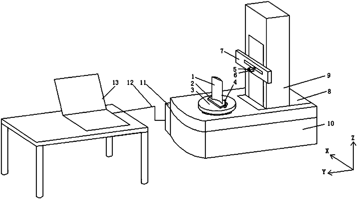
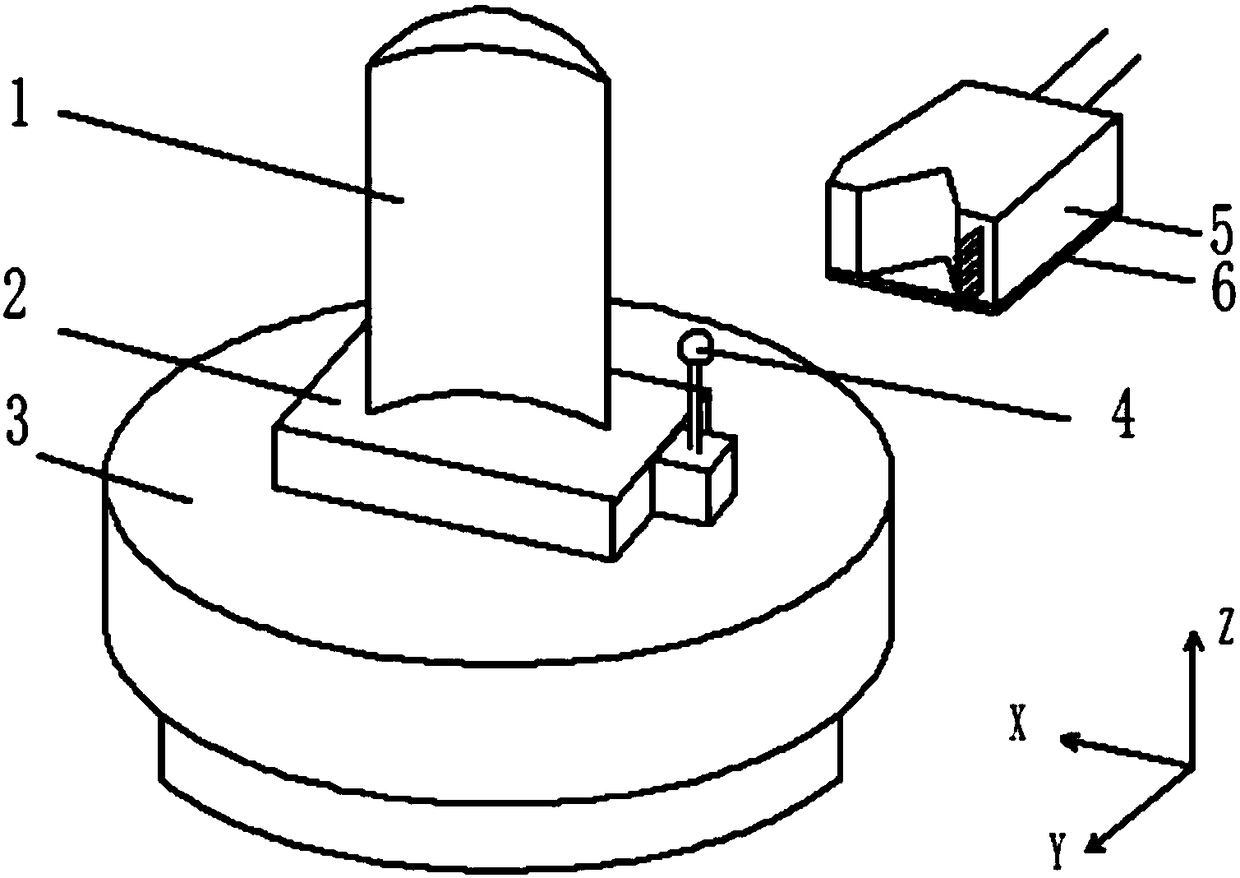
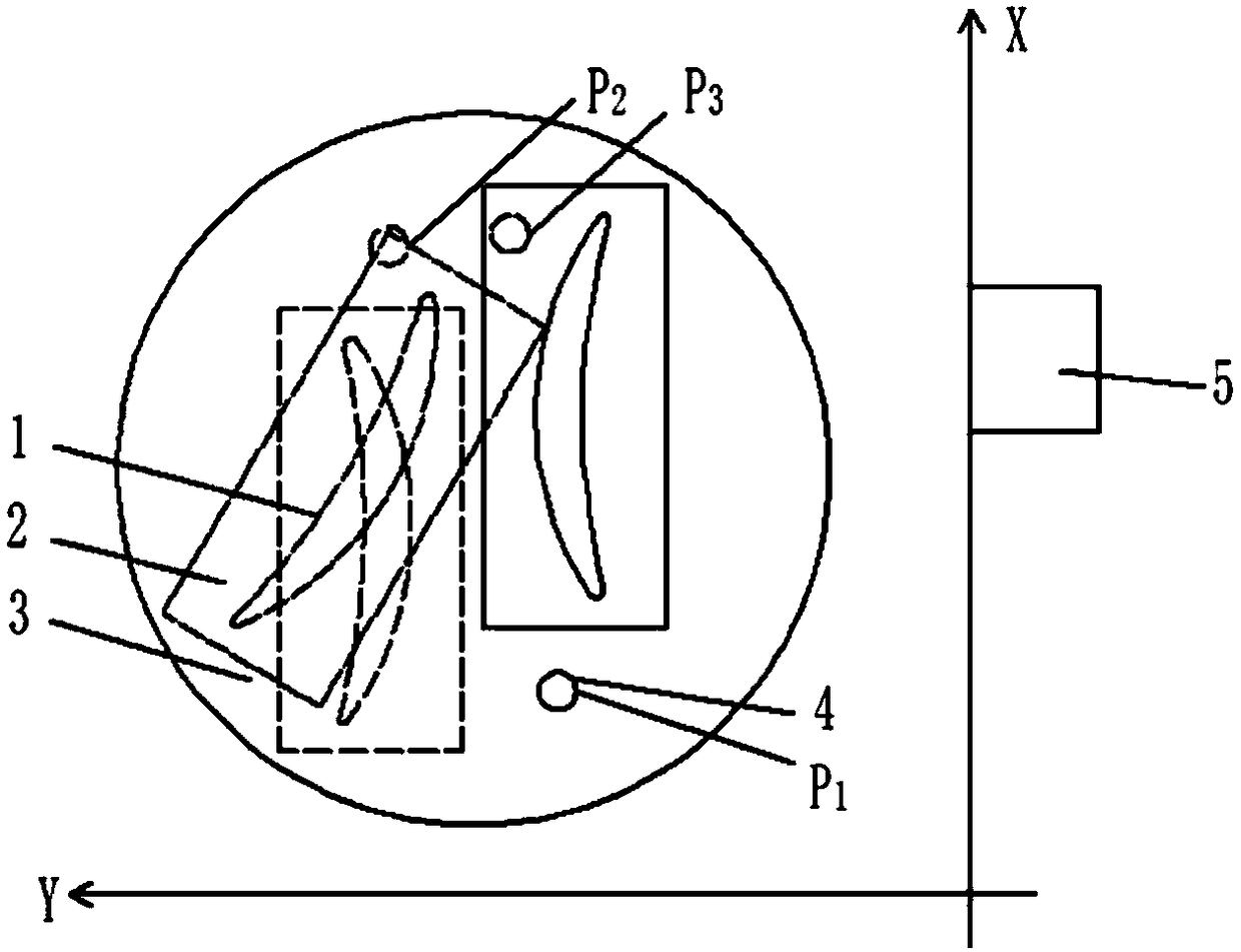
The invention discloses an all-data measuring and splicing method and an all-data measuring and splicing device for a blade molded surface. According to the method, firstly, a blade is clamped on a rotary table and the blade scanning is carried out by means of a sensor clamped in different sensor clamping modes according to the characteristics of the blade molded surface. Therefore, the all-data acquisition of the blade molded surface is completed. After that, by means of a standard ball arranged on the rotary table, conversion coordinates are worked out according to the coordinates of the sphere center of the standard ball and the coordinates of the sphere center of the standard ball after being translated, and the center of the rotary table. In this way, the data splicing of the blade molded surface in different coordinate systems is completed. Finally, complete blade three-dimensional point cloud data are obtained. The method and the device are simple to operate, high in acquisitionspeed, high in efficiency, simple and convenient in algorithm and easy to implement. According to the invention, a new reference is provided for the detection of the blade molded surface. Meanwhile,the method and the device have important guiding significance for realizing the measurement of other objects with complex molded surfaces.

Description

technical field [0001] The invention belongs to the technical field of blade profile detection, and in particular relates to a blade profile full-data measurement splicing method and device. Background technique [0002] The blade is a key part of an aero-engine, which undertakes the important task of converting heat energy into mechanical energy. The quality of the blade is the guarantee of the quality of the whole machine, and the shape error of the blade directly affects the energy conversion efficiency of the whole machine. The blade profile is generally a variable cross-section torsion surface with a large scale span, strong force, and large load. The leading and trailing edges of the blade are the key parameters of the blade design. Usually, the leading and trailing edges are designed as circular arcs, and its manufacturing precision directly determines the aerodynamic performance of the blade. [0003] The profile of the blade is a twisted curved surface with variab...

Claims


Application Information

Patent Timeline
IPC IPC(8): G01B11/24
CPCG01B11/24
Inventor 李兵闫潇辛美婷陈磊魏翔
Owner XI AN JIAOTONG UNIV
Learn More