
Automatic pressure regulating and locking structure of full-automatic high-speed precision die cutting machine

An automatic pressure regulation and automatic locking technology, applied in metal processing and other directions, can solve problems such as inability to regulate pressure, machine suffocation, pressure instability, etc. Effect

Pending Publication Date: 2018-06-12
DONGGUAN LING IND
View PDF7 Cites 0 Cited by
  • Summary
  • Abstract
  • Description
  • Claims
  • Application Information

AI Technical Summary

Problems solved by technology

[0003] Its disadvantages are: 1. The accuracy of manual pressure adjustment is poor. If the manual pressure adjustment is too much, the whole section of the material or the steel knife will be damaged or the machine will be suffocated. If the manual pressure adjustment is too small, the material will not be cut, and it will take many times Slowly adjust to achieve the effect of die-cutting. It takes a long time to adjust the machine and waste materials; 2. After the pressure is adjusted, it needs to be locked manually. When locking manually, the locking force is small and the lock is not tight. As a result, the pressure of the machine is unstable during operation. When the locking force is too large when manually locking, the locking screw will be twisted, resulting in the failure to adjust the pressure.

Method used


Image

  • Automatic pressure regulating and locking structure of full-automatic high-speed precision die cutting machine
  • Automatic pressure regulating and locking structure of full-automatic high-speed precision die cutting machine

Examples


Embodiment Construction

[0022] It should be noted that, in the case of no conflict, the embodiments of the present invention and the features in the embodiments can be combined with each other.

[0023] In describing the present invention, it should be understood that the terms "center", "longitudinal", "transverse", "upper", "lower", "front", "rear", "left", "right", " The orientations or positional relationships indicated by "vertical", "horizontal", "top", "bottom", "inner" and "outer" are based on the orientations or positional relationships shown in the drawings, and are only for the convenience of describing the present invention and Simplified descriptions, rather than indicating or implying that the device or element referred to must have a particular orientation, be constructed and operate in a particular orientation, and thus should not be construed as limiting the invention. In addition, the terms "first", "second", etc. are used for descriptive purposes only, and should not be understood ...


PUM


Abstract

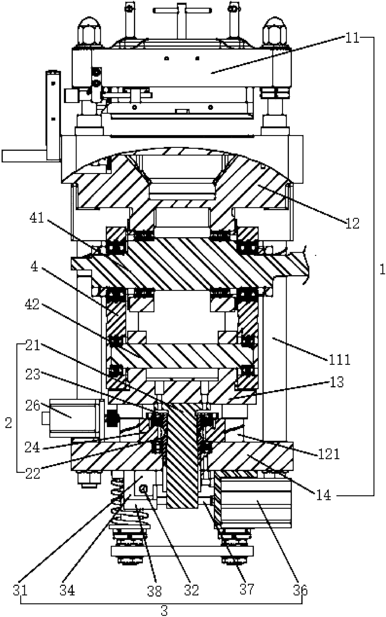
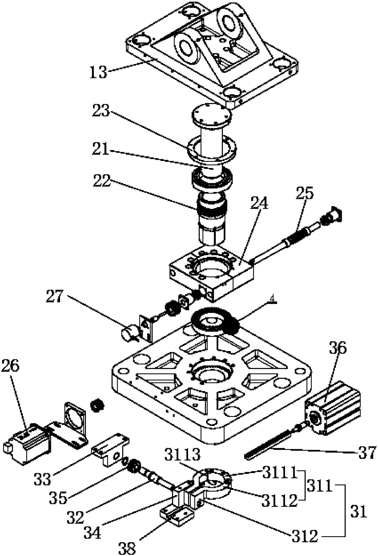
The invention provides an automatic pressure regulating and locking structure of a full-automatic high-speed precision die cutting machine. The full-automatic high-speed precision die cutting machinecomprises a die cutting assembly and a pressure regulating assembly. The die cutting assembly comprises an upper die base and a lower die base, and a lifting seat is arranged on the lower side of thelower die base. The lifting seat is connected with the lower die base through a main eccentric shaft, and the lifting seat is driven by the main eccentric shaft to vertically ascend and descend. A lifting bottom plate is mounted on the lower side of the lifting seat through the pressure regulating assembly, and the lifting bottom plate is fixedly connected with the upper die base through a liftingguide column. The pressure regulating assembly comprises a lifting adjusting shaft, and the lifting adjusting shaft is fixed to the bottom face of the lifting seat. An external thread is arranged onthe column face of the lifting adjusting shaft, and the column face of the lifting adjusting shaft is in threaded connection with a worm wheel. The worm wheel is rotationally connected with the lifting bottom plate and is axially fixed, and the worm wheel is engaged with a worm driven by a pressure regulating driving device. Therefore, precise pressure regulation is achieved.

Description

technical field [0001] The invention belongs to the field of die-cutting machines, and in particular relates to an automatic pressure-regulating and automatic-locking structure of a fully automatic high-speed precision die-cutting machine. Background technique [0002] The working principle of the die-cutting machine is: use the template carved by steel knife, metal mold, steel wire or steel plate, apply a certain pressure through the embossing plate, and cut the printed matter or cardboard into a certain shape. The main parts of the die-cutting machine are the die-cutting platen and the press-cutting mechanism. The processed sheet is between the two, and the finishing technology of die-cutting is completed under the action of pressure. At present, the flat-press die-cutting machines on the market generally use manual pressure regulation, manual locking, manual pressure regulation, simple structure and convenient maintenance. [0003] Its disadvantages are: 1. The accuracy ...

Claims


Application Information

Patent Timeline
Patent Type & Authority Applications(China)
IPC IPC(8): B26F1/44B26D7/26
CPCB26D7/2614B26D7/2628B26F1/44
Inventor 林燕华
Owner DONGGUAN LING IND
Learn More