Diffractive multi-focal ocular lens and method for manufacturing diffractive multi-focal ocular lens
An ophthalmic lens, multi-focal technology, applied in the direction of glasses/protective glasses, glasses/goggles, intraocular lens, etc., can solve problems such as halo
- Summary
- Abstract
- Description
- Claims
- Application Information
AI Technical Summary
Problems solved by technology
Method used
Image
Examples
example 8
[0203] Simulation as a contact lens
[0204] The eye optical system is arranged in the order of contact lens, cornea, aqueous humor, iris, lens, vitreous body, and retina, and determines the refractive index and shape based on human eye data. In addition, determine the refractive power and pupil diameter of the contact lens as described below.
[0205] Contact lens 0th order diffracted light refraction degree (diopter): 0D
[0206] Pupil diameter: diameter 3.8mm
[0207] In addition, like the simulation of the intensity distribution on the optical axis, the simulation related to the above-mentioned point spread function was also performed with an incident light wavelength of 546 nm, and the light source was a point light source at an infinite distance.
[0208] During an example-based explanation of a specific example of the present invention obtained based on the method and conditions of computational simulation as described above, an overview of the structure and character...
example 1
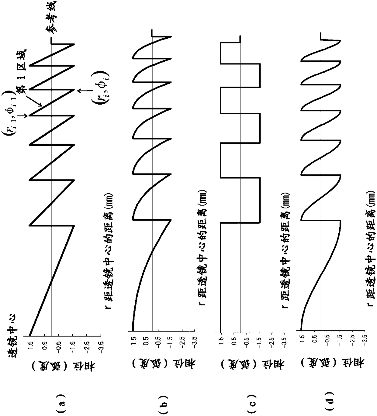
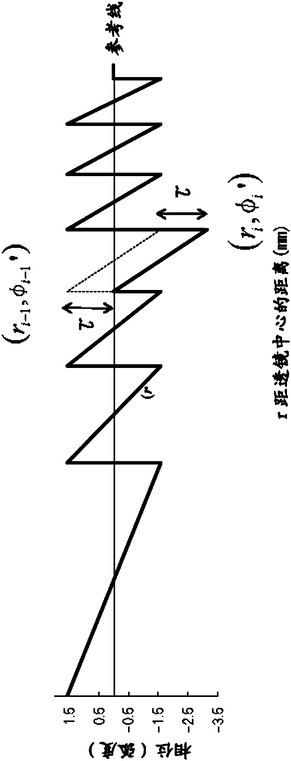
[0230] Example 1 based on the present invention is shown below. The inventive distribution of Example 1 has the aforementioned Table 1 and Figure 7 Distribution shown in A. At the same time, Comparative Example 1 for Table 1 and Figure 5 Each region in the standard distribution shown in A has a phase constant of h = 0.6, and in Table 2 and Figure 7 In A, the standard distribution as Comparative Example 1 is shown by a dotted line.
[0231] Table 2
example 2
[0241] Example 2 shows another pattern related to Example 1. The radius of the constituent region of the standard distribution of Comparative Example 2 is the same as that of Comparative Example 1, but as shown in Table 3 and Figure 8 As shown in A, reset the phase constant and phase shift of the blaze. The intensity distribution on the optical axis of the standard distribution used in Comparative Example 2 is given by Figure 8 The dotted line in B shows. As in Comparative Example 1, the standard distribution of Comparative Example 2 generates peaks at 0D, 3D, and 4D positions. For Comparative Example 2, the standard distribution itself has almost no generation of multi-order light, and compared with Comparative Example 1, the 0D peak intensity for hyperopia is increased. The standard distribution of Comparative Example 2 can also be a multifocal ophthalmic lens in which hyperopia, myopia and intermediate vision are feasible. However, for this comparative example 2, the ...
PUM
 Abstract
Description
Claims
Application Information
 - R&D
- Intellectual Property
- Life Sciences
- Materials
- Tech Scout
- Unparalleled Data Quality
- Higher Quality Content
- 60% Fewer Hallucinations
Browse by: Latest US Patents, China's latest patents, Technical Efficacy Thesaurus, Application Domain, Technology Topic, Popular Technical Reports.
© 2025 PatSnap. All rights reserved.Legal|Privacy policy|Modern Slavery Act Transparency Statement|Sitemap|About US| Contact US: help@patsnap.com


