
Device for improving OVD sintering efficiency and prolonging service life of lead rod and OVD sintering method

A lead-rod and life-span technology, used in manufacturing tools, glass manufacturing equipment, etc., can solve the problems of high price of He, reduce sintering efficiency, and prolong sintering time, and achieve the effect of reducing consumption, reducing sintering cost, and shortening sintering time.

Pending Publication Date: 2018-06-08
TONGDING INTERCONNECTION INFORMATION CO LTD +1
View PDF6 Cites 4 Cited by
  • Summary
  • Abstract
  • Description
  • Claims
  • Application Information

AI Technical Summary

Problems solved by technology

However, the traditional sintering equipment structure only has a quartz cover plate at the furnace mouth. Since the lead rod enters the high-temperature zone in the high-temperature environment of sintering, it is easy to be stretched and thinned. It is necessary to replace the new sintering lead rod, which takes time for installation, inspection, and maintenance. Tests have reduced the sintering efficiency; sintering lead rods are expensive and frequently increase production costs; most of the He and Cl2 gases introduced into the furnace are pumped away with the draft, He is expensive and increases production costs, and toxic Cl2 leakage is harmful Great safety hazard; a large amount of heat is continuously drawn out with the draft, which increases the load on the heating element and prolongs the sintering time
Increase the load of the exhaust system and increase the production cost of the optical fiber preform

Method used

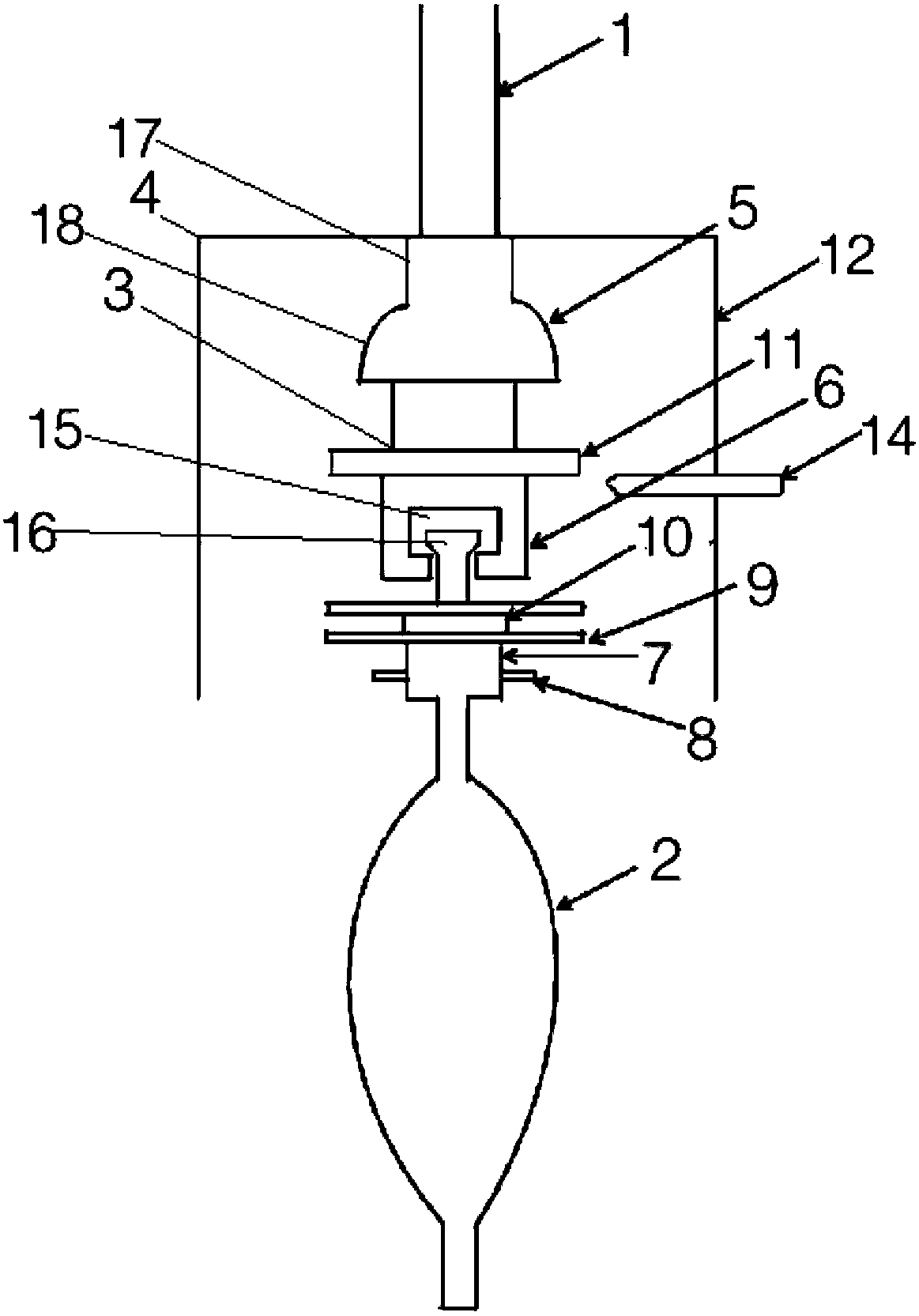

Image

  • Device for improving OVD sintering efficiency and prolonging service life of lead rod and OVD sintering method
  • Device for improving OVD sintering efficiency and prolonging service life of lead rod and OVD sintering method
  • Device for improving OVD sintering efficiency and prolonging service life of lead rod and OVD sintering method

Examples


Embodiment Construction

[0037] It should be noted that, in the case of no conflict, the embodiments of the present invention and the features in the embodiments can be combined with each other.

[0038] In describing the present invention, it should be understood that the terms "center", "longitudinal", "transverse", "upper", "lower", "front", "rear", "left", "right", The orientations or positional relationships indicated by "vertical", "horizontal", "top", "bottom", "inner", "outer", etc. are based on the orientation or positional relationships shown in the drawings, and are only for the convenience of describing the present invention Creation and simplification of description, rather than indicating or implying that the device or element referred to must have a specific orientation, be constructed and operate in a specific orientation, and therefore should not be construed as limiting the invention. In addition, the terms "first", "second", etc. are used for descriptive purposes only, and should no...


PUM


Abstract

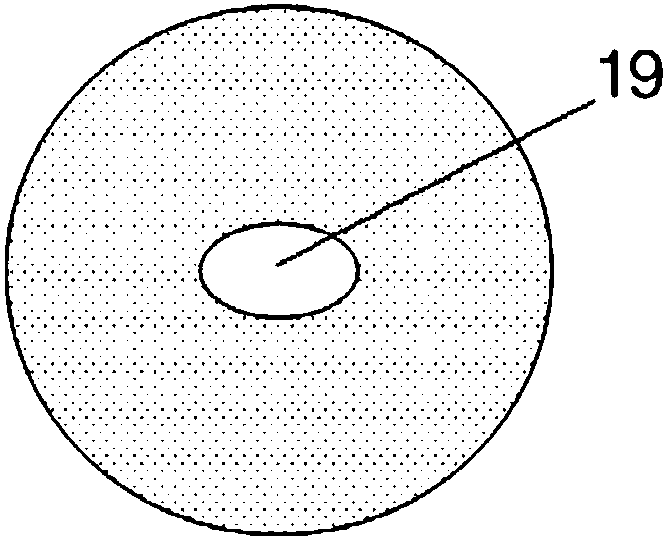
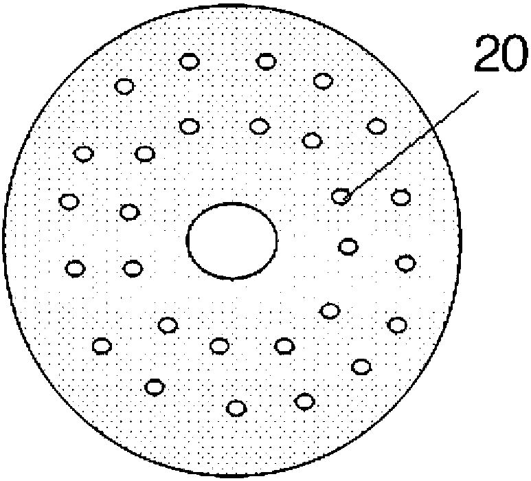
The invention provides a device for improving the OVD sintering efficiency and prolonging the service life of a lead rod. The device comprises a flow-limiting and heat-insulating unit arranged betweenthe lead rod and a prefabricated rod loose body, and an air suction unit arranged by corresponding to the flow-limiting and heat-insulating unit, wherein the flow-limiting and heat-insulating unit comprises a connecting coupler mounted at the lower end of the lead rod; an adapter is connected to a connector at the lower end of the connecting coupler; the prefabricated rod loose body is connectedto the bottom of the adapter through a pin; two layers of flow-limiting plates corresponding to each other up and down are arranged on the adapter; a quartz ring is arranged between the two flow-limiting plates; a heat-insulating plate is arranged on the adapter. In the device, through the two layers of flow-limiting plates and the heat-insulating plate, heat is effectively insulated so as to keepthe lead rod away from a high-temperature zone, so that the lead rod is maximally avoided from being thinned by stretching at high temperature; in addition, the consumption of a raw material gas is effectively reduced, the sintering time is shortened, and the sintering cost of a prefabricated rod is reduced.

Description

technical field [0001] The invention belongs to the technical field of research and development and manufacture of optical fiber preform rods, and in particular relates to a device and method for improving OVD sintering efficiency and prolonging the service life of lead rods. Background technique [0002] The sintering of the OVD preform loose body is the most important process in the preform preparation process. This process directly affects various quality indicators of the optical fiber preform and optical fiber, including preform diameter uniformity, bubble gas line defects, and optical fiber loss. Wait. [0003] The process principle of OVD sintering is to dehydrate and sinter in a high temperature environment of 1500°C to finally form a transparent glass preform. The so-called dehydration refers to the reaction of silanol-hydrogen bonding group (Si-OH) with chlorine gas (Cl2) to generate glass particles. The chemical reaction equation is as follows: [0004] 2Si-OH+C...

Claims


Application Information

Patent Timeline
Patent Type & Authority Applications(China)
IPC IPC(8): C03B37/014
CPCC03B37/0146
Inventor 沈小平崔德运向德成何炳贺程程谈悠儒满小忠朱坤
Owner TONGDING INTERCONNECTION INFORMATION CO LTD
Learn More