
Article incorporating a knitted component with zonal stretch limiter

a technology of stretch limiter and component, applied in the field of articles of footwear, can solve the problems of limited stretching and excessive tightness of footwear 100/b> on a specific area of the wearer's foo

Active Publication Date: 2016-12-06
NIKE INC
View PDF166 Cites 30 Cited by
  • Summary
  • Abstract
  • Description
  • Claims
  • Application Information

AI Technical Summary

Benefits of technology

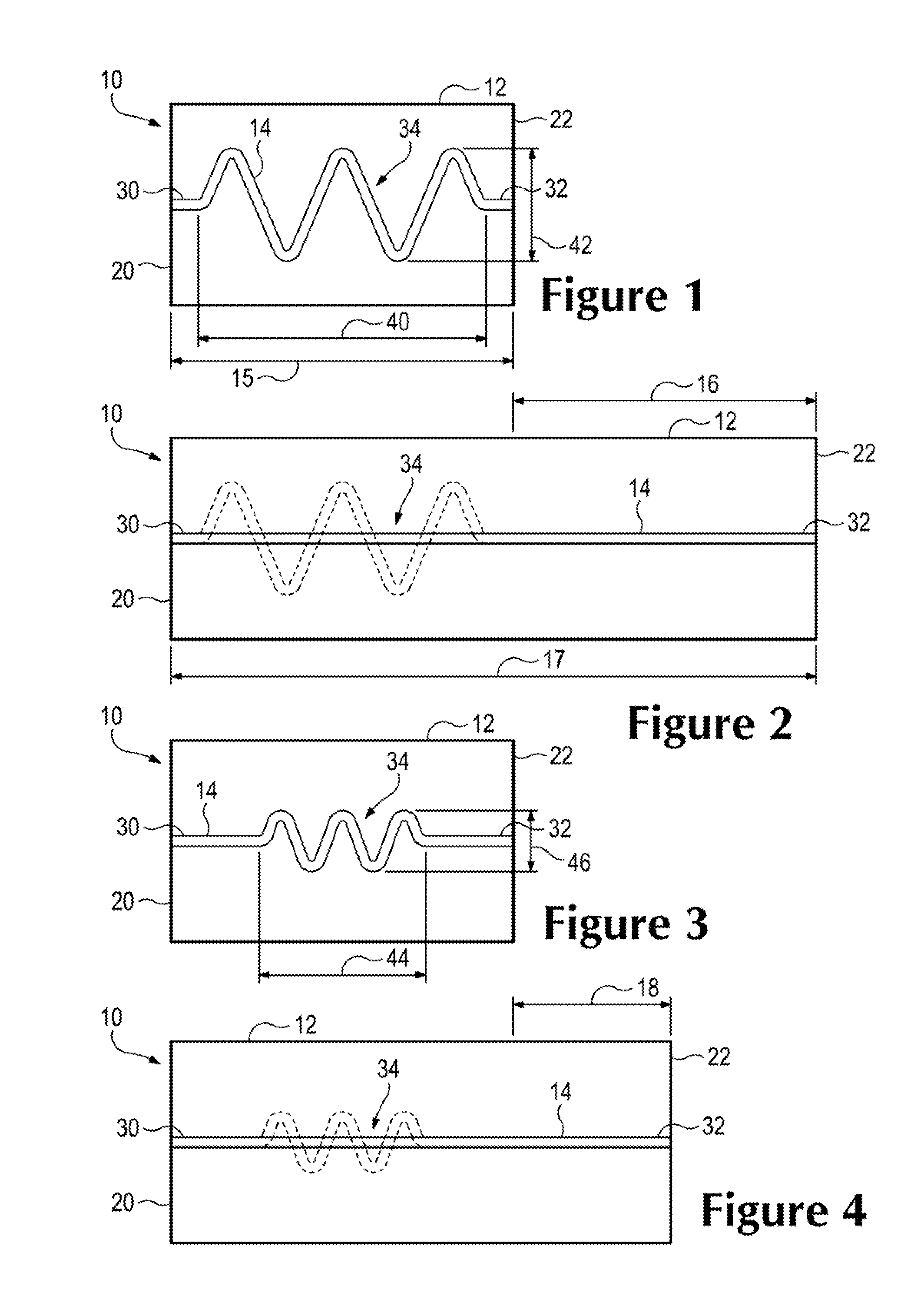
[0004]An article is disclosed that includes a knitted component formed of unitary knit construction. The knitted component includes a knit element that is configured to stretch between a neutral position and a stretched position. The knitted component also includes a tensile strand that is formed of unitary knit construction with the knit element. The tensile strand is at least partially inlaid within the knit element. The tensile strand includes a portion that is arranged as a stretch limiter element that is configured to move between a slack position and a taut position as the knit element moves between the neutral position and the stretched position. The stretch limiter element is in the slack position when the knit element is in the neutral position, and the stretch limiter element is in the taut position when the knit element is in the stretched position to prevent stretch of the knit element beyond the stretched position.
[0005]Also, an article is disclosed that includes a knitted component formed of unitary knit construction. The knitted component includes a knit element with a first portion and a second portion. The first portion is stretchable relative to the second portion between a neutral position and a stretched position. The knitted component also includes a tensile strand that is formed of unitary knit construction with the knit element. The tensile strand extends across at least one of the first portion and the second portion of the knit element. The tensile strand is at least partially inlaid within the knit element. The tensile strand includes a portion that is arranged as a stretch limiter element that is configured to move between a slack position and a taut position as the first portion stretches between the neutral position and the stretched position. The stretch limiter element is in the slack position when the first portion is in the neutral position. The stretch limiter element is in the taut position when the first portion is in the stretched position to prevent stretch of the first portion beyond the stretched position.

Problems solved by technology

Moreover, in some embodiments, the footwear 100 may be too tight on a specific area of the wearer's foot.
As such, these articles can stretch to maintain comfort, and the stretching can be limited to ensure the article remains secured to the wearer's body.

Method used


Image

  • Article incorporating a knitted component with zonal stretch limiter
  • Article incorporating a knitted component with zonal stretch limiter
  • Article incorporating a knitted component with zonal stretch limiter

Examples


Embodiment Construction

[0043]Example embodiments will now be described more fully with reference to the accompanying drawings.

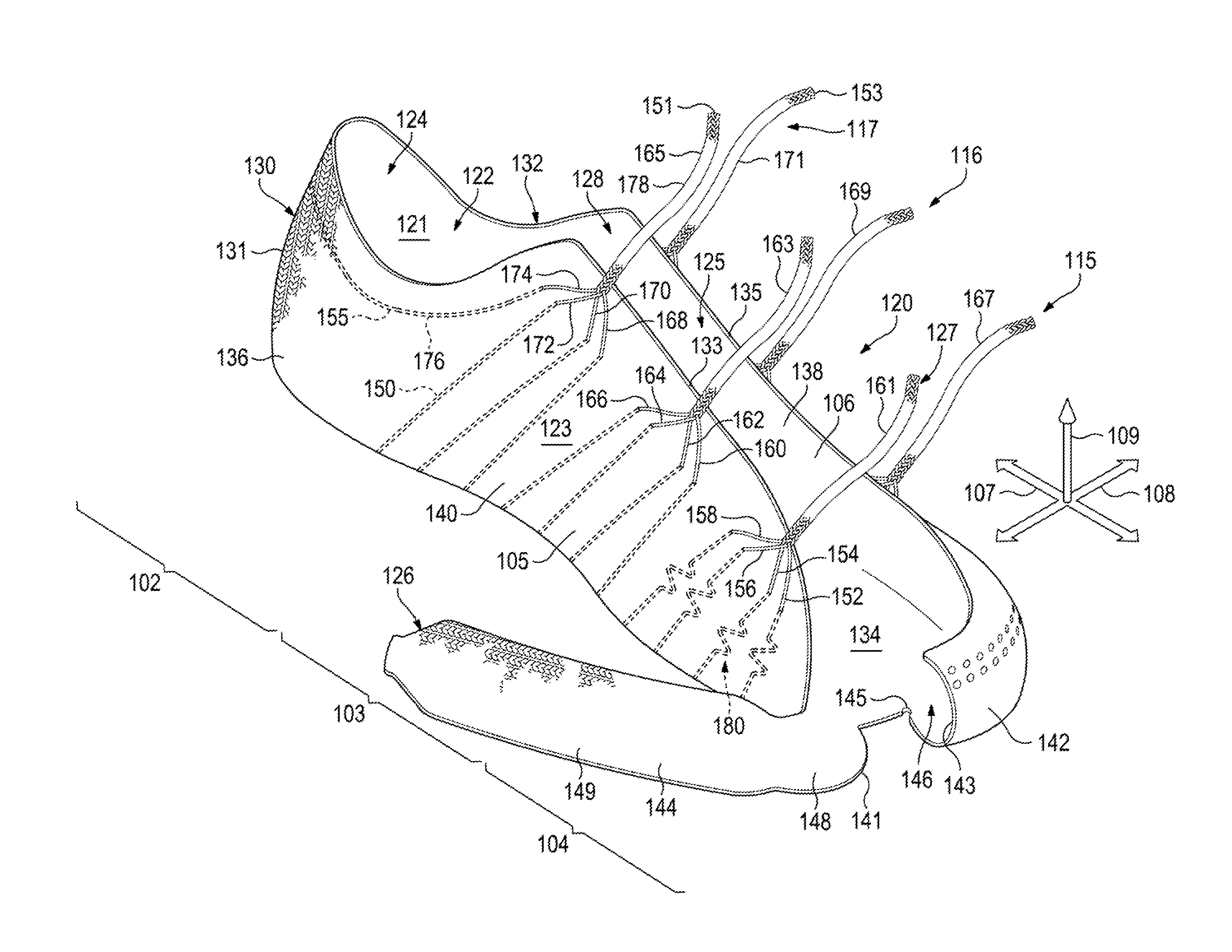
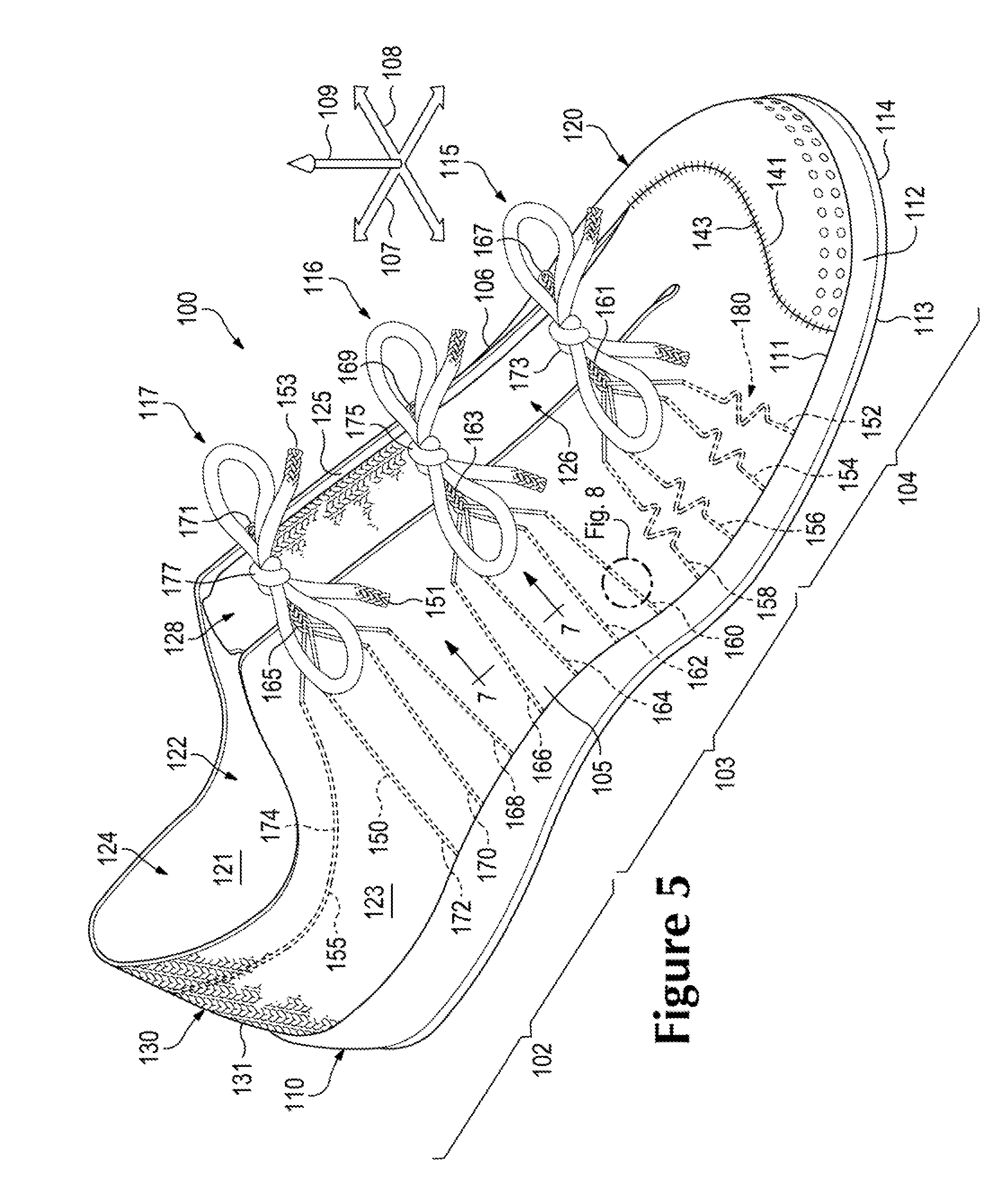
[0044]The following discussion and accompanying figures disclose a variety of concepts related to a knitted component. The knitted component can be incorporated into a wide variety of articles, such as an article of footwear, an article of apparel, sports equipment, and other objects.

[0045]The knitted component can include various features that allow stretching of one or more areas of the knitted component. The knitted component can stretch, for example, to fit and conform to an underlying surface. More specifically, in some embodiments, the knitted component can be incorporated into an article of footwear, and the knitted component can stretch to fit and conform to the wearer's foot. Also, the joints in the foot can articulate, the musculature of the foot can flex, and / or the foot can otherwise move to cause stretching of the knitted component. Moreover, the footwear can impact th...


PUM


Abstract

An article includes a knitted component. The knitted component includes a knit element that is configured to stretch between a neutral position and a stretched position. The knitted component also includes a tensile strand. The tensile strand is at least partially inlaid within the knit element. The tensile strand includes a portion that is arranged as a stretch limiter element that is configured to move between a slack position and a taut position as the knit element moves between the neutral position and the stretched position. The stretch limiter element is in the slack position when the knit element is in the neutral position, and the stretch limiter element is in the taut position when the knit element is in the stretched position to prevent stretch of the knit element beyond the stretched position.

Description

BACKGROUND[0001]Conventional articles of footwear generally include two primary elements, an upper and a sole structure. The upper is secured to the sole structure and forms a void on the interior of the footwear for comfortably and securely receiving a foot. The sole structure is secured to a lower area of the upper, thereby being positioned between the upper and the ground. In athletic footwear, for example, the sole structure may include a midsole and an outsole. The midsole often includes a polymer foam material that attenuates ground reaction forces to lessen stresses upon the foot and leg during walking, running, and other ambulatory activities. Additionally, the midsole may include fluid-filled chambers, plates, moderators, or other elements that further attenuate forces, enhance stability, or influence the motions of the foot. The outsole is secured to a lower surface of the midsole and provides a ground-engaging portion of the sole structure formed from a durable and wear-r...

Claims


Application Information

Patent Timeline
Patent Type & Authority Patents(United States)
IPC IPC(8): D04B1/12A43B1/04A43B23/02A43B23/04
CPCA43B1/04A43B23/0265A43B23/04D04B1/123D10B2501/043D10B2403/032A43B23/025A43B23/0275D04B1/24
Inventor PODHAJNY, DANIEL A.CROSS, TORY M.
Owner NIKE INC
Learn More