
Full contact test circuit for TFT (Thin Film Transistor) array substrate

A technology of array substrate and test circuit, applied in the field of display panel detection, to achieve the effects of improving the success rate, preventing electrostatic discharge, and strong water and oxygen barrier ability

Active Publication Date: 2018-06-05
WUHAN CHINA STAR OPTOELECTRONICS SEMICON DISPLAY TECH CO LTD
View PDF6 Cites 22 Cited by
  • Summary
  • Abstract
  • Description
  • Claims
  • Application Information

AI Technical Summary

Problems solved by technology

[0008] C, as the number of test terminals 301 in the test chip 300 increases, the metal area occupied by all test terminals 301 is relatively large, and the conductivity of the metal is good, so there is a risk of electrostatic discharge (Electro-Static Discharge, ESD).
[0009] In addition, if image 3 As shown, after the TFT array substrate is fabricated, the test terminal 301 in the test chip 300 is covered by an insulating organic layer 900 to prevent impurity particles from falling or water and oxygen from entering, so the existing TFT array substrate full-contact test Lines are only allowed in figure 2 In the case shown, the source / drain of the TFT in the TFT array substrate is manufactured and then tested, and it cannot be image 3 In the case shown, the TFT array substrates are all manufactured and then tested

Method used


Image

  • Full contact test circuit for TFT (Thin Film Transistor) array substrate
  • Full contact test circuit for TFT (Thin Film Transistor) array substrate
  • Full contact test circuit for TFT (Thin Film Transistor) array substrate

Examples


Embodiment Construction

[0030] In order to further illustrate the technical means adopted by the present invention and its effects, the following describes in detail in conjunction with preferred embodiments of the present invention and accompanying drawings.

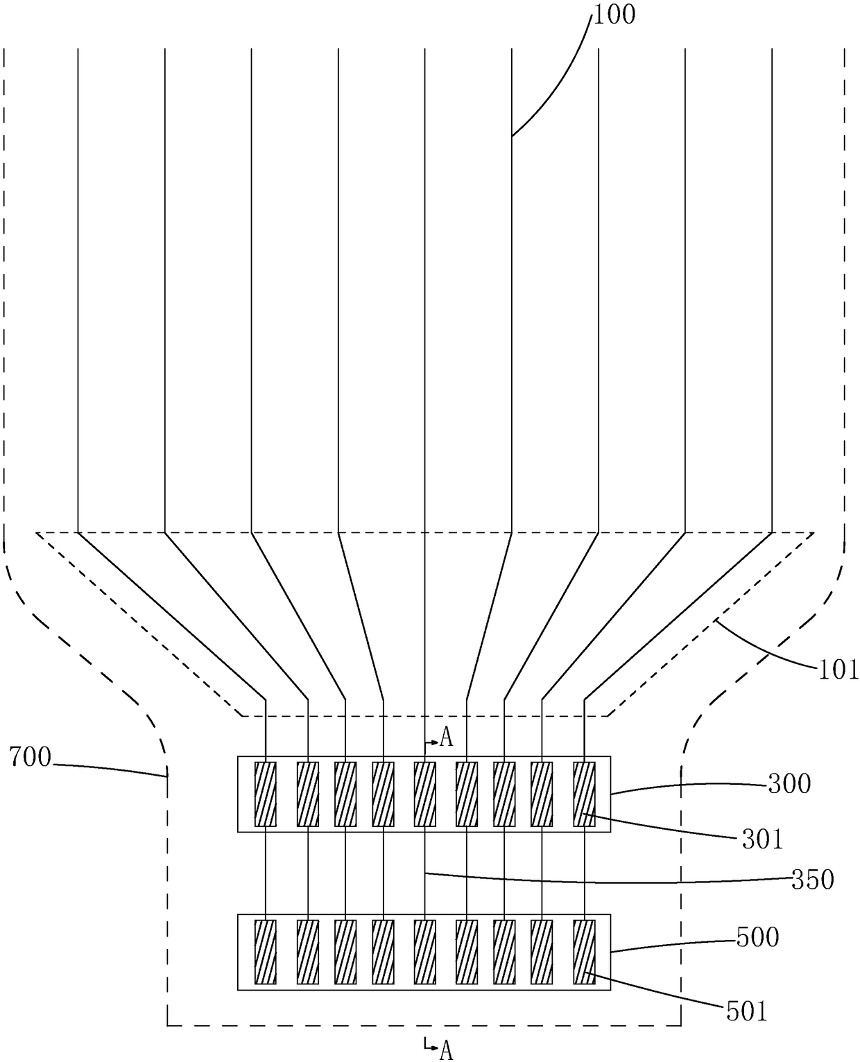
[0031] The invention provides a full-contact test circuit for a TFT array substrate. Please also see Figure 4 and Figure 5 The TFT array substrate full-contact test circuit of the present invention includes a plurality of data lines 1, a driver chip 3 arranged outside the fan-out area (Fanout) 11 of the plurality of data lines 1, and a driver chip 3 arranged in the driver chip 3. The test chip 5 on the side away from the fan-out area 11 . Different from the prior art where both the test chip and the driving chip are set within the panel cutting boundary, the TFT array substrate full-contact test circuit of the present invention sets the driving chip 3 within the panel cutting boundary 7, and the The test chip 5 is set outside the panel cu...


PUM


Abstract

The invention provides a full contact test circuit for a TFT (Thin Film Transistor) array substrate, which is characterized in that a test chip (5) is arranged outside a panel cutting boundary line (7), the size of each test terminal (51) on the test chip (5) and the distance between the adjacent test terminals (51) are allowed to be increased, and the success rate of enabling test equipment to becontacted with the test terminals (51) can be improved; the test chip (5) is cut off during panel cutting, wires (35) connecting the test terminals (51) and driving terminals (31) on a driving chip (3) are made of a conductor (S) located at the same layer with an active layer of a TFT in the TFT array substrate, and the risk of line corrosion and electrostatic discharge occurred after panel cutting can be prevented; and the test terminals (51) need not to be covered with an insulating organic layer because the test chip (5) is cut off during panel cutting, so that the test is allowed to be performed both after the source / drain electrode of the TFT in the TFT array substrate is manufactured and under a condition that the whole TFT array substrate is manufactured.

Description

technical field [0001] The invention relates to the technical field of display panel detection, in particular to a full-contact test circuit for a TFT array substrate. Background technique [0002] Organic Light Emitting Display (OLED) has self-illumination, no backlight, high contrast, thin thickness, wide viewing angle, fast response, can be used for flexible panels, wide operating temperature range, structure It is considered to be an emerging application technology for the next generation of flat panel displays due to its excellent characteristics such as simple manufacturing process. [0003] OLED display panels can be divided into passive matrix (Passive Matrix, PM) OLED and active matrix (Active Matrix, AM) OLED according to the driving type, namely direct addressing and thin film transistor (Thin Film Transistor, TFT) matrix Two classes of addressing. The AMOLED display panel includes a TFT array substrate on which pixels (Pixels) arranged in an array are arranged....

Claims


Application Information

Patent Timeline
IPC IPC(8): H01L21/66H01L27/12
CPCH01L22/30H01L27/1214
Inventor 陈彩琴
Owner WUHAN CHINA STAR OPTOELECTRONICS SEMICON DISPLAY TECH CO LTD
Learn More