


Quick Research
Generate reliable direction feasibility study reports for your R&D in just a few steps.

Technical Q&A
Discover and master advanced knowledge NOW. Basics, ideas, possibilities, all at once.

Find Solutions
As an expert in R&D theories, this can generate solutions to your technical problems instantly.

Evaluate Feasibility
Analyze your overall solution with one click, know your potential R&D risks in advance.

Monitor Landscape
Get weekly tech updates, stay abreast of the latest tech innovations and key insights.
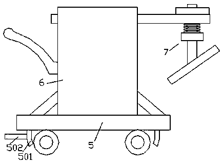
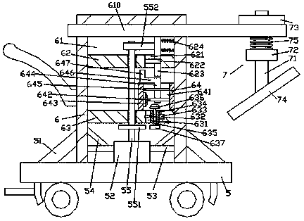
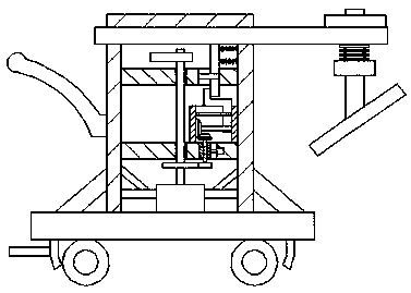
Special tamping device for road slope
A compaction device and technology for slope surfaces, which are used in soil protection, construction, infrastructure engineering, etc., can solve the problems of inability to realize compaction work on slope surfaces, increase work time, and increase economic costs, and achieve simple structure and reduced work. time, and the effect of reducing economic costs
- Summary
- Abstract
- Description
- Claims
- Application Information
AI Technical Summary
Problems solved by technology
Method used
Image

Examples
Embodiment Construction
[0022] Such as figure 1 — Figure 4As shown, a special tamping device for road slopes according to the present invention includes a mobile car body 5 and a tamping body 6 fixedly installed on the top of the mobile car body 5 . The placement cavity 61 on the bottom end surface, the interior of the placement cavity 61 is symmetrically provided with a first cross beam 62 and a second cross beam 63 extending left and right, and the extension ends on the left and right sides of the first cross beam 62 and the second cross beam 63 are respectively It is fixedly connected with the inner walls of the left and right sides of the placement chamber 61, and the top end surface of the mobile vehicle body 5 at the bottom of the placement chamber 61 is fixed with a first motor 52 extending into the placement chamber 61. The first motor 52 is connected to the top of the first rotating shaft 55 extending upwards. The extension section of the top of the first rotating shaft 55 runs through the...
PUM
 Abstract
Description
Claims
Application Information
 - R&D Engineer
- R&D Manager
- IP Professional
- Industry Leading Data Capabilities
- Powerful AI technology
- Patent DNA Extraction
Browse by: Latest US Patents, China's latest patents, Technical Efficacy Thesaurus, Application Domain, Technology Topic, Popular Technical Reports.
© 2024 PatSnap. All rights reserved.Legal|Privacy policy|Modern Slavery Act Transparency Statement|Sitemap|About US| Contact US: help@patsnap.com