Method and device for operating a hydraulic brake system, brake system

A braking system, hydraulic technology, applied in the direction of braking safety system, braking control system, braking transmission device, etc., can solve problems such as increased operating current

Active Publication Date: 2021-10-22
ROBERT BOSCH GMBH
View PDF6 Cites 0 Cited by
  • Summary
  • Abstract
  • Description
  • Claims
  • Application Information

AI Technical Summary

Problems solved by technology

This is the case, for example, when the hydraulic support is removed and thus the actuator requires more force to move the brake piston, so that the operating current of the actuator thus increases beyond the expected value

Method used


Image

  • Method and device for operating a hydraulic brake system, brake system
  • Method and device for operating a hydraulic brake system, brake system
  • Method and device for operating a hydraulic brake system, brake system

Examples


Embodiment Construction

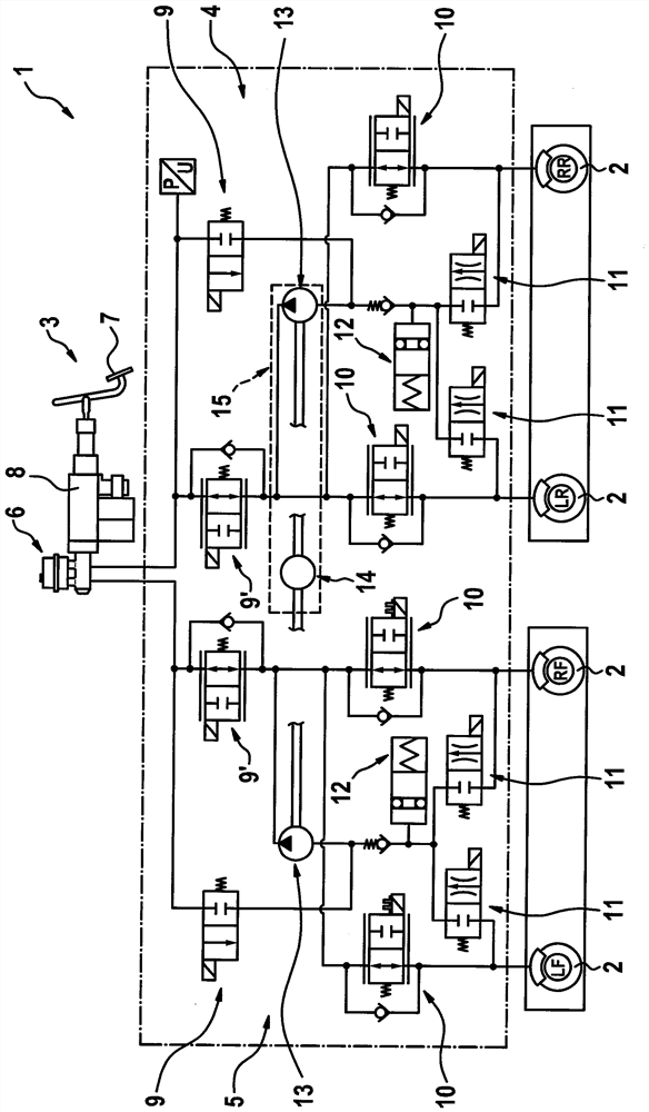
[0020] figure 1 A simplified illustration shows a brake system 1 for a motor vehicle which is not shown in detail here. Braking system 1 has a plurality of wheel brakes 2 which can be actuated by the driver of the motor vehicle via a brake pedal arrangement 3 which serves as an operating brake. Here, wheel brakes 2 are denoted by LR, RF, LR and RR, whereby their position or assignment on the motor vehicle is explained, wherein LR stands for left rear, RF stands for right front, LF stands for left front, and RR Indicates rear right. Two brake circuits 4 and 5 are formed between the brake pedal arrangement 3 and the wheel brakes 2 , wherein the brake circuit 4 is assigned to the wheel brakes LR and RR and the brake circuit 5 is assigned to the wheel brake LF and RF. The two brake circuits 4 and 5 are designed identically, so that the structure of the two brake circuits 4 , 5 will be explained in more detail below with reference to the brake circuit 4 .

[0021] The brake cir...


PUM


Abstract

The invention relates to a method for operating a hydraulic braking system of a motor vehicle, the braking system having wheel brakes, a brake pedal arrangement and a pressure generator for actuating the wheel brakes, and an electromechanical actuator for actuating the wheels Brakes, by means of pressure generators and actuators that can generate a force that is used to move the brake pistons of the wheel brakes to actuate the wheel brakes, to adjust the parking brake function the pressure generators and actuators are controlled in such a way that they together generate the total clamp tightening force, in order to determine the functional capability of the hydraulic braking system, the operating current of the actuator (i 23 ). It is provided that the pressure generator is actuated during adjustment in such a way that the hydraulic pressure can be maintained for a predetermined duration (tp‑tp 2 ) is modulated in order to de-load or load the actuator, and the operating current of the actuator for this duration is evaluated in order to determine the functional capability of the braking system (i 23 ).

Description

technical field [0001] The invention relates to a method for operating a hydraulic brake system of a motor vehicle, wherein the brake system has at least one wheel brake, a brake pedal arrangement and at least one controllable pressure generator as well as associated an electromechanical actuator of the wheel brake, the pressure generator for the hydraulic actuation of the wheel brake, the actuator for actuating the wheel brake, wherein a force can be generated by the pressure generator and the actuator respectively, The force is used to move a brake piston of the wheel brake to actuate the wheel brake, wherein the pressure generator and the actuator are controlled in such a way that they jointly generate a force on the wheel for adjusting the parking brake function. The total clamping force at the brake, and wherein, in order to determine the functional capability of the hydraulic brake system, the operating current of the actuator is monitored during the adjustment. Backgr...

Claims


Application Information

Patent Timeline
Patent Type & Authority Patents(China)
IPC IPC(8): B60T13/74B60T13/12B60T17/22
CPCB60T13/12B60T13/745B60T17/221B60T13/74B60T17/22B60T2270/413B60T8/32B60T8/4872B60T8/172B60T8/266B60T8/94
Inventor E.曼赫茨H.沃尔夫
Owner ROBERT BOSCH GMBH
Why Eureka
Try Eureka