Tension test equipment with protection function

A tensile test and protection function technology, applied in the direction of using stable tension/pressure to test the strength of materials, measuring devices, instruments, etc., can solve the problems of accidental breakage of metal wires, injury to inspectors, and easy collapse of fixed ends. Achieve the effect of fast sliding speed, fast stretching speed and good safety performance

Inactive Publication Date: 2018-06-01
成都市新都立新金属制造有限公司
View PDF0 Cites 1 Cited by
  • Summary
  • Abstract
  • Description
  • Claims
  • Application Information

AI Technical Summary

Problems solved by technology

[0004] The technical problem to be solved by the present invention is that when the metal is stretched, the fixed end of the metal wire and the device is easy to collapse and hurt the testing personnel. The purpose is to provide a tensile testing device with a protective function to solve the accidental breakage of the metal wire during the detection process. Or the problem of detaching from the equipment and hurting the testing personnel

Method used


Image

  • Tension test equipment with protection function
  • Tension test equipment with protection function

Examples


Embodiment 1

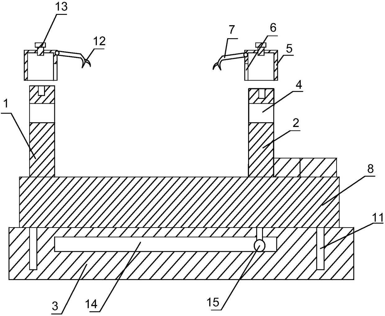
[0024] like figure 1 , figure 2 As shown, the tensile testing equipment with protective function of the present invention includes a testing machine body, and the testing machine body includes a first fixed seat 1 and a second fixed seat 2 placed in parallel, and the metal wire to be tested is connected to the first fixed seat 1, the second fixed seat 2 Between the second fixed seat 2, the first fixed seat 1 and the second fixed seat 2 are connected with a horizontally placed support seat 3, the first fixed seat 1 and the second fixed seat 2 are all vertical to the support seat 3, and the first fixed seat 2 is vertical to the support seat 3. The seat 1 is fixedly connected with the support seat 3, and the second fixed seat 2 is slidingly connected with the support seat 3. To the moving motive mechanism, the first fixed seat 1 and the second fixed seat 2 are provided with relative through holes 4, and the tops of the first fixed seat 1 and the second fixed seat 2 are equipped...

Embodiment 2

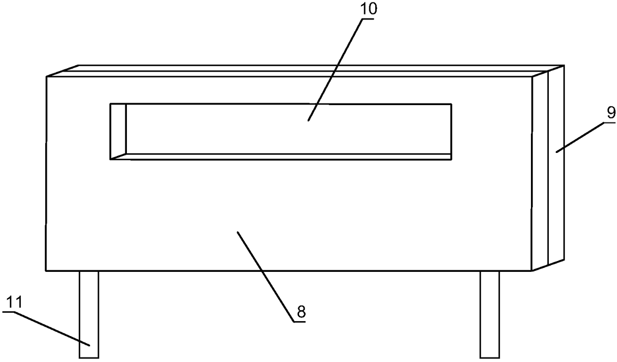
[0027] Based on Embodiment 1, a baffle 8 is connected to the support seat 3, and the baffle 8 is located on one side of the first fixed seat 1 and the second fixed seat 2, and the height of the baffle 8 is higher than that of the first fixed seat 1 and the second fixed seat. The height of the seat 2, the length of the baffle plate 8 is longer than the furthest distance between the first fixed seat 1 and the second fixed seat 2, the bottom of the baffle plate 8 is connected with many pins 11 inserted into the support seat 3, and the support seat 3 is provided with A jack that mates with pin 11. The side walls of the baffle plate 8 close to the first fixed seat 1 and the second fixed seat 2 are completely covered with a foam layer 9, the baffle plate 8 and the foam layer 9 are provided with interconnected through grooves, and transparent silica gel is installed inside the through grooves Pad 10.

[0028] The baffle plays a protective role for the inspectors. After installing th...


PUM


Abstract

The invention discloses tension test equipment with a protection function. The tension test equipment comprises a test machine body, wherein the test machine body comprises a first fixed seat and a second fixed seat in parallel arrangement; a metal wire is connected between the first fixed seat and the second fixed seat; a support seat is connected with the lower parts of the first fixed seat andthe second fixed seat; the first fixed seat is fixedly connected with the support seat; the second fixed seat is glidingly connected with the support seat; a movable machine mechanism enabling the second fixed seat to move in a direction facing or backing to the first fixed seat on the support seat is connected with the second fixed seat; opposite through holes are formed in the first fixed seat and the second fixed seat; a case sleeves the top end of each of the first fixed seat and the second fixed seat; the through holes are covered by the case; the bottom of the case is provided with a notch through which a metal wire passes; a hook claw connected with the outer wall of the metal wire is hinged to one side, facing the metal wire, of the case; a plurality of barbs are connected with thehook claw. The tension test equipment provided by the invention has good safety performance.

Description

technical field [0001] The invention relates to a tensile testing machine, in particular to tensile testing equipment with protective functions. Background technique [0002] Tensile testing machine is also known as universal material testing machine. Universal testing machine is a mechanical testing machine used for static load, tension, compression, bending, shearing, tearing, peeling and other mechanical performance tests of instruments and equipment for various materials. It is suitable for plastic sheets, pipes, Various physical and mechanical performance tests of profiled materials, plastic films and rubber, wire and cable, steel, glass fiber and other materials are used for material development, and are indispensable testing equipment for physical property tests, teaching research, quality control, etc. Important components, different materials require different fixtures. [0003] Tensile strength is an important property of metal wire. After the metal wire is proce...

Claims


Application Information

Patent Timeline
Patent Type & Authority Applications(China)
IPC IPC(8): G01N3/02G01N3/08
CPCG01N3/02G01N3/08G01N2203/0017G01N2203/0067G01N2203/028
Inventor 李岩
Owner 成都市新都立新金属制造有限公司
Why Eureka
Try Eureka