
Special-shaped expansion block molded surface numerical control milling fixture and machining method

A CNC milling and block-expanding technology, which is applied in the direction of manufacturing tools, metal processing equipment, metal processing machinery parts, etc., can solve the problem of high processing costs, increased parts processing costs, positioning, clamping, alignment, and tool setting. High integration requirements and other issues, to achieve the effect of easy loading and unloading of parts, ensuring consistency, and low manufacturing difficulty

Inactive Publication Date: 2018-06-01
CHINA HANGFA GUIZHOU LIYANG AVIATION POWER CO LTD
View PDF4 Cites 5 Cited by
  • Summary
  • Abstract
  • Description
  • Claims
  • Application Information

AI Technical Summary

Problems solved by technology

[0004] (1) The five-axis machining center is used to process the profile of the expanding block. The processing cost of this processing method is high, which greatly increases the processing cost of parts;
[0005] (2) The three-axis machining center is used to process the profile of the expanding block, and the processing cost and labor intensity of the workers are greatly reduced under the condition of ensuring the machining accuracy, but the four-in-one requirements for positioning, clamping, alignment, and tool setting higher

Method used


Image

  • Special-shaped expansion block molded surface numerical control milling fixture and machining method
  • Special-shaped expansion block molded surface numerical control milling fixture and machining method

Examples


Embodiment Construction

[0028] The technical solution of the present invention is further described below in conjunction with the accompanying drawings, but the scope of protection is not limited to the above.

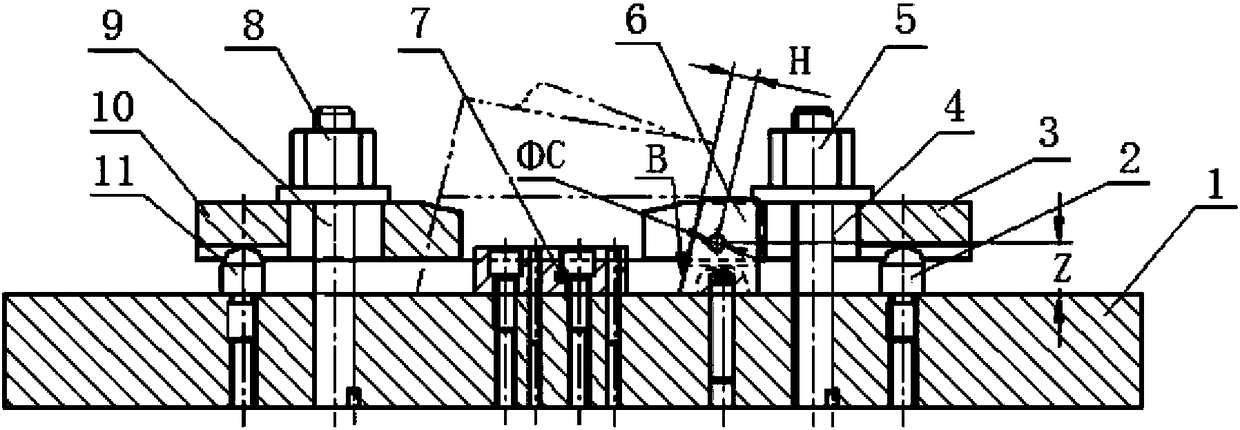
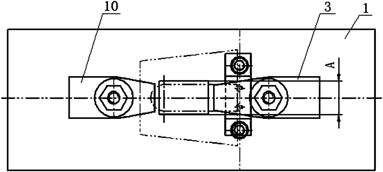
[0029] Such as figure 1 , figure 2 As shown, the CNC milling fixture for special-shaped expansion block surface according to the present invention includes a bottom plate 1, a right support 2, a right pressure plate 3, a left pressure plate 10, and a left support 11. The right pressure plate 3 is installed by a right screw 4 On the bottom plate 1, the right support 2 is installed between the bottom plate 2 and the right pressure plate 3, and is located on the right side of the right screw 4; the left pressure plate 10 is installed on the bottom plate 1 through the left screw 9, and the left support 2 is installed on the bottom plate 2 and Between the left pressure plate 10 and on the right side of the left screw 9, a positioning block 6 is also provided inside the right pressure plate 3. The p...


PUM


Abstract

The invention discloses a special-shaped expansion block molded surface numerical control milling fixture and a machining method. The fixture comprises a bottom plate, a right support, a right pressing plate, a left pressing plate and a left support. The right pressing plate is mounted on the bottom plate through a right screw rod. The right support is mounted between the bottom plate and the right pressing plate and located on the right side of the right screw rod. The left pressing plate is mounted on the bottom plate through a left screw rod. The left support is mounted between the bottom plate and the left pressing plate and located on the left side of the left screw rod. A locating block is arranged on the inner side of the right pressing plate. The machining method comprises the steps of (1) design and manufacturing of the fixture; (2) alignment of the fixture; (3) clamping of an expansion block; (4) establishing of an expansion block digital model; and (5) machining of expansionblock molded surfaces. The special-shaped expansion block molded surface numerical control milling fixture is simple in structure and low in manufacturing difficulty. The fixture is used for conducting numerical control machining, parts are convenient to dismantle, the interchangeability is good; the machining consistency of the expansion block part molded surfaces can be effectively ensured, andmeanwhile, the labor intensity of workers is reduced.

Description

Technical field [0001] The invention belongs to the technical field of mechanical processing, and specifically relates to a fixture and a processing method for numerical control milling processing of a profiled expansion block surface. Background technique [0002] At present, the forming method of engine heat shield type parts is combined welding after segment pressing or welding after roll forming. However, the roundness and dimensional accuracy of parts using the above forming method are not easy to guarantee. [0003] Based on the above-mentioned two molding methods, the roundness and dimensional accuracy of parts are not easy to guarantee, and it is necessary to use the bulging process method to correct the shape and dimensional accuracy of engine heat shield parts to meet the assembly requirements. The bulging mold expansion blocks are usually special-shaped parts, and the processing of such expansion block parts generally adopts the following methods: [0004] (1) The five-ax...

Claims


Application Information

Patent Timeline
Patent Type & Authority Applications(China)
IPC IPC(8): B23Q3/06B23C3/00
CPCB23Q3/062B23C3/00
Inventor 韩前宏刘军郑廷俊王意豪周琦浩
Owner CHINA HANGFA GUIZHOU LIYANG AVIATION POWER CO LTD
Learn More