A Simple Device and Method for Dynamically Measuring the Jitter of Rotating Electrode Bar
A rotating electrode, dynamic measurement technology, applied in the field of powder metallurgy industry, can solve problems such as affecting the quality of atomized powder, difficulty in accurate and stable bar operation, affecting the safety of equipment operation, and the stability of the molten pool, so as to achieve convenient judgment and facilitate quantitative The effect of analysis
- Summary
- Abstract
- Description
- Claims
- Application Information
AI Technical Summary
Problems solved by technology
Method used
Image
Examples
Embodiment 1
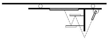
[0055] Use a qualified Ti6Al4V bar with a diameter of 54.98mm, adjust the optical path to meet the requirements of the upper reflector, the lower reflector, and the observation glass parallel to the axis of the bar, and keep the angle between the optical path of the laser transmitter and the vertical line at 30° (or the included angle is 30°), the measured straightness of the bar, and the runout of the outer circle in the middle is 0.022mm. Rotate at 24000rpm, and the diameter of the observation window circle is 22mm after calibration. The bar starts to jump, and the transient state of the bar rising is as follows: Figure 5 As shown, the light spot moves to the right of the observation glass circle, and the transient state of the bar sinking is as follows Figure 6 As shown, the spot moves to the left of the viewing glass circle. Rotate at 30000rpm, calibrate the diameter of the observed glass circle to be 30mm, and find that the bar is still rotating stably. Do not change ...
Embodiment 2
[0057] Use a qualified 304 stainless steel bar with a diameter of 78.90mm, adjust the optical path to meet the requirements of the upper reflector, the lower reflector, and the observation glass parallel to the axis of the bar, and keep the angle between the optical path of the laser transmitter and the vertical line at 50°. The straightness of the bar is measured, and the outer circle in the middle runs out of 0.025mm. Rotate at 20000rpm, and the diameter of the observation window circle is calibrated to 34mm. The bar starts to jump, and the transient state of the bar rising is as follows: Figure 5 As shown, the light spot moves to the right of the observation glass circle, and the transient state of the bar sinking is as follows Figure 6 As shown, the spot moves to the left of the viewing glass circle. Without changing the geometric parameters, replace the second unknown bar, and increase the rotation speed to 20,000rpm. It is observed that the diameter of the spot track ...
Embodiment 3
[0059] Use a qualified TA15 rod with a diameter of 75.12mm, adjust the optical path to meet the requirements of the upper reflector, the lower reflector, and the observation glass parallel to the axis of the bar, and keep the angle between the optical path of the laser transmitter and the vertical line at 80°. The straightness of the bar is measured, and the outer circle in the middle runs out 0.020mm. Rotate at 18000rpm, and the diameter of the observation window circle is 26mm after calibration. The bar starts to jump, and the transient state of the bar rising is as follows: Figure 5 As shown, the light spot moves to the right of the observation glass circle, and the transient state of the bar sinking is as follows Figure 6 As shown, the spot moves to the left of the viewing glass circle. Without changing the geometric parameters, replace the second unknown bar, and increase the rotation speed to 18000rpm. It is observed that the diameter of the spot track circle of the o...
PUM
 Abstract
Description
Claims
Application Information
 - R&D
- Intellectual Property
- Life Sciences
- Materials
- Tech Scout
- Unparalleled Data Quality
- Higher Quality Content
- 60% Fewer Hallucinations
Browse by: Latest US Patents, China's latest patents, Technical Efficacy Thesaurus, Application Domain, Technology Topic, Popular Technical Reports.
© 2025 PatSnap. All rights reserved.Legal|Privacy policy|Modern Slavery Act Transparency Statement|Sitemap|About US| Contact US: help@patsnap.com


