A drying device for the production and processing of auto parts
What is Al technical title?
Al technical title is built by PatSnap Al team. It summarizes the technical point description of the patent document.
A technology for auto parts and drying equipment, applied in drying, drying machine, drying gas arrangement, etc., can solve the problems of increasing power consumption and reducing drying efficiency, so as to reduce consumption, improve efficiency, and improve drying efficiency. The effect of dry efficiency
Active Publication Date: 2019-12-06
秀山县秀环机械制造有限公司
View PDF4 Cites 0 Cited by
Summary
Abstract
Description
Claims
Application Information
AI Technical Summary
This helps you quickly interpret patents by identifying the three key elements:
Problems solved by technology
Method used
Benefits of technology
Problems solved by technology
[0003] In the prior art, most of the drying devices for parts are placed inside the trough drying device, and the parts are dried by hot air circulation, but because the position of the parts in the drying device is always the same, resulting in zero The windward side of the parts is dried first, and the windward side of the parts is still in a wet state. It takes a continuous drying time for the parts to completely dry the parts, which reduces the drying efficiency and also reduces the drying efficiency. increase power consumption
Method used
Image
Click on the blue label to locate the original text in one second.
Reading with bidirectional positioning of images and text.
Examples
Embodiment Construction
[0027] The technical solutions in the embodiments of the present invention will be clearly and completely described below in conjunction with the accompanying drawings in the embodiments of the present invention. Obviously, the described embodiments are only a part of the embodiments of the present invention, rather than all the embodiments. Based on the embodiments of the present invention, all other embodiments obtained by those of ordinary skill in the art without creative work shall fall within the protection scope of the present invention.
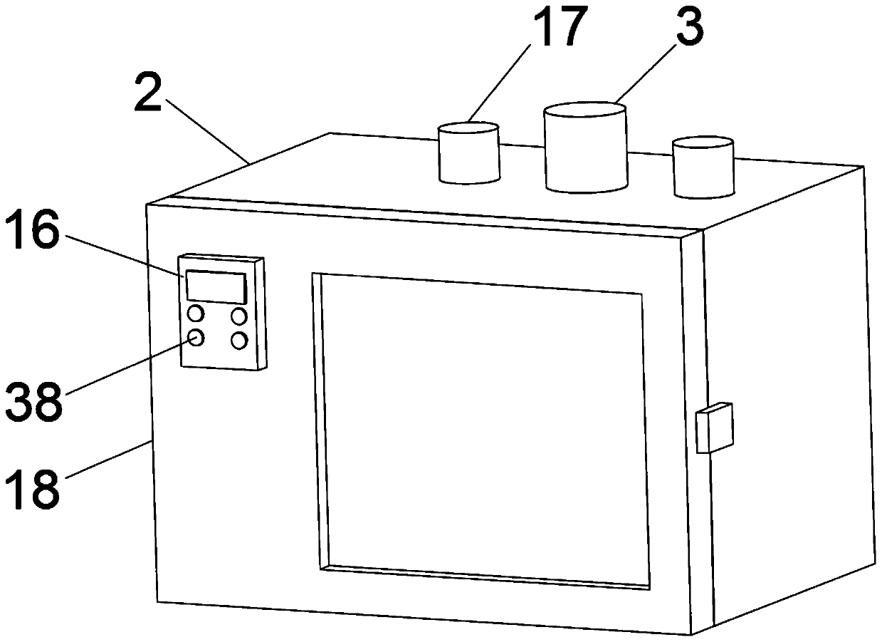
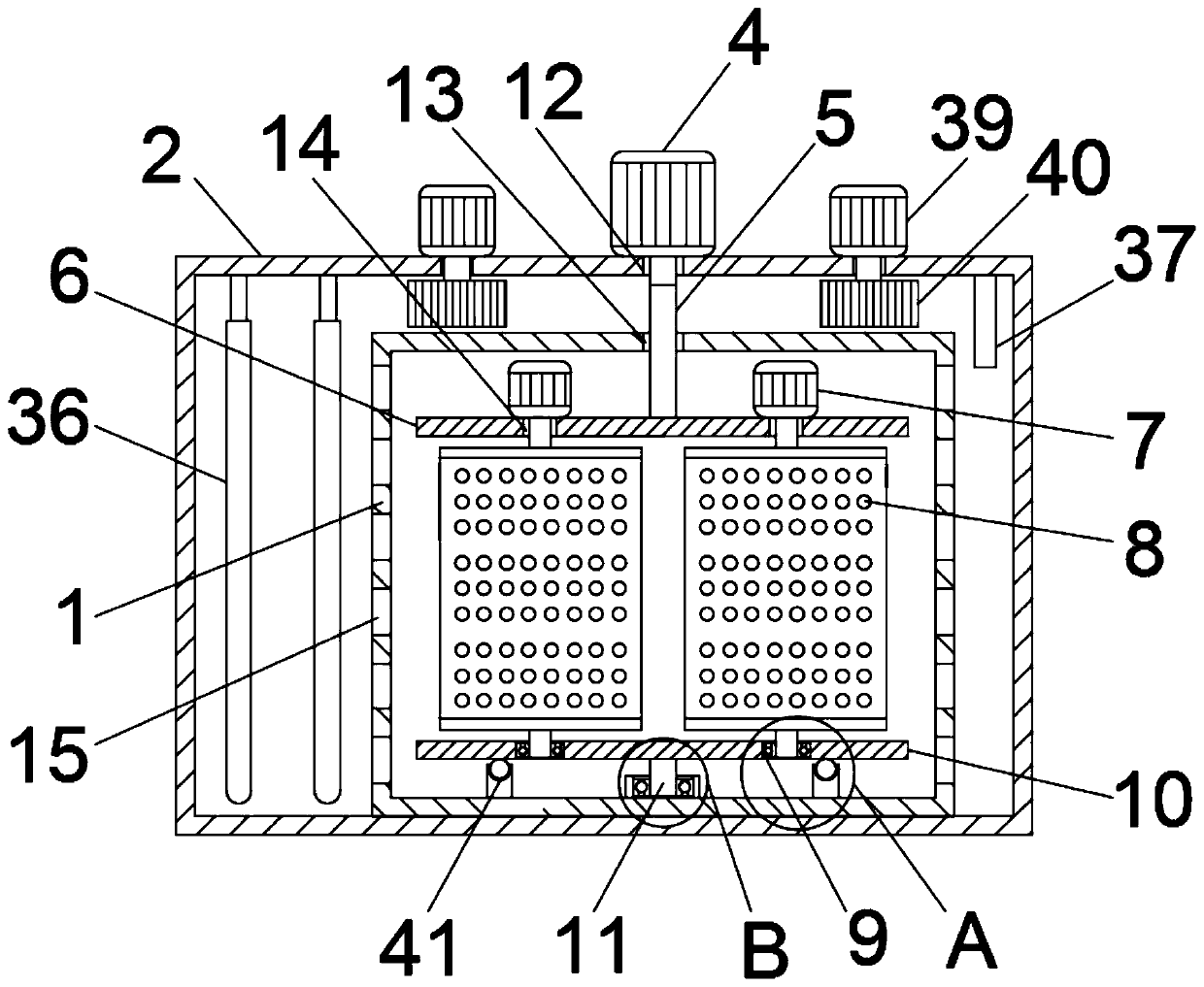
[0028] See Figure 1-8 , The present invention provides a technical solution: a drying device for the production and processing of auto parts, comprising an inner liner 1, a shell 2, a turning device 3, a temperature control device 16 and a negative pressure device 17, the inner liner 1 The bottom is fixed to the inner wall of the bottom of the housing 2. The inner tank 1 is fixed with a turning device 3, the turning device 3 includes a ...
PUM
Abstract
The invention discloses a drying device for production and processing of automobile parts. The drying device comprises a liner, a shell, a flipping device, a temperature control device and a negativepressure device, and the bottom of the liner and the inner wall of the bottom of the shell are fixed; the flipping device is fixed inside the liner and comprises a revolution motor, a connecting shaft, a mounting plate, an autorotation motor, a drying cylinder, a connecting piece, a supporting plate and a supporting seat; the revolution motor is fixed to the top of the shell, a first through holeis formed in the position, corresponding to the revolution motor, of the top of the shell, and an output shaft of the revolution motor penetrates through the first through hole to be fixed to the connecting shaft; and a second through hole is formed in the position, corresponding to the first through hole, of the top of the liner, and the end, away from the revolution motor, of the connecting shaft penetrates through the second through hole to be fixed to the mounting plate. According to the drying device for production and processing of the automobile parts, the automobile parts can be made to conduct autorotation and revolution in the liner through the flipping device, the outer sides of the parts can be dried simultaneously, the drying efficiency of the parts is improved, and energy consumption is also reduced.
Description
Technical field [0001] The invention relates to the technical field of automobile parts production, in particular to a drying device for the production and processing of automobile parts. Background technique [0002] In the production process of auto parts, it is often necessary to clean the processed auto parts. After the cleaning of the parts is completed, the parts need to be dried. [0003] Most of the drying devices for parts in the prior art place the parts inside the slot drying device, and dry the parts through hot air circulation, but the position of the parts in the drying device is always the same, resulting in zero The windward side of the component is dried first, and the windy side of the component is still wet. It needs continuous drying time for the component to completely dry the component, which reduces the drying efficiency and also Increase the consumption of electrical energy. To this end, we propose a drying device for the production and processing of auto ...
Claims
Application Information
Patent Timeline
Application Date:The date an application was filed.
Publication Date:The date a patent or application was officially published.
First Publication Date:The earliest publication date of a patent with the same application number.
Issue Date:Publication date of the patent grant document.
PCT Entry Date:The Entry date of PCT National Phase.
Estimated Expiry Date:The statutory expiry date of a patent right according to the Patent Law, and it is the longest term of protection that the patent right can achieve without the termination of the patent right due to other reasons(Term extension factor has been taken into account ).
Invalid Date:Actual expiry date is based on effective date or publication date of legal transaction data of invalid patent.