
Lifting mechanism for ultra-thin display bracket

A display bracket and lifting mechanism technology, which is applied in the direction of machines/supports, supporting machines, mechanical equipment, etc., can solve the problems of unsuitable ultra-thin display bracket products, restrictions on the use of lifting mechanisms, and large friction plates.

Pending Publication Date: 2018-05-29
FUJIAN RICHES ELECTRONICS SCI & TECH
View PDF1 Cites 2 Cited by
  • Summary
  • Abstract
  • Description
  • Claims
  • Application Information

AI Technical Summary

Problems solved by technology

However, the cross section of the friction plate is approximately an open U-shaped structure, so limited by this structural factor, its dimension (that is, the thickness of the friction plate) perpendicular to the U-shaped opening direction is relatively large, which limits the design range of the display bracket
[0004] In recent years, due to the progress in the mechanism design of electronic products, more and more electronic products are pursuing the appearance of light and thin brackets. Therefore, the use of the lifting mechanism in the prior art is limited to a certain extent, and it cannot be applied to ultra-thin display bracket products.

Method used


Image

  • Lifting mechanism for ultra-thin display bracket
  • Lifting mechanism for ultra-thin display bracket

Examples


Embodiment Construction

[0024] In order to further explain the technical solution of the present invention, the present invention will be described in detail below through specific examples.

[0025] In the description of the present invention, it should be noted that the orientations indicated by the terms "vertical", "upper", "lower", "inner", "outer" etc. are based on the orientations shown in the drawings, and are only for convenience The invention is described without implying or indicating that referenced components must have a particular orientation, operate in a particular orientation and configuration, and therefore should not be construed as limiting the invention.

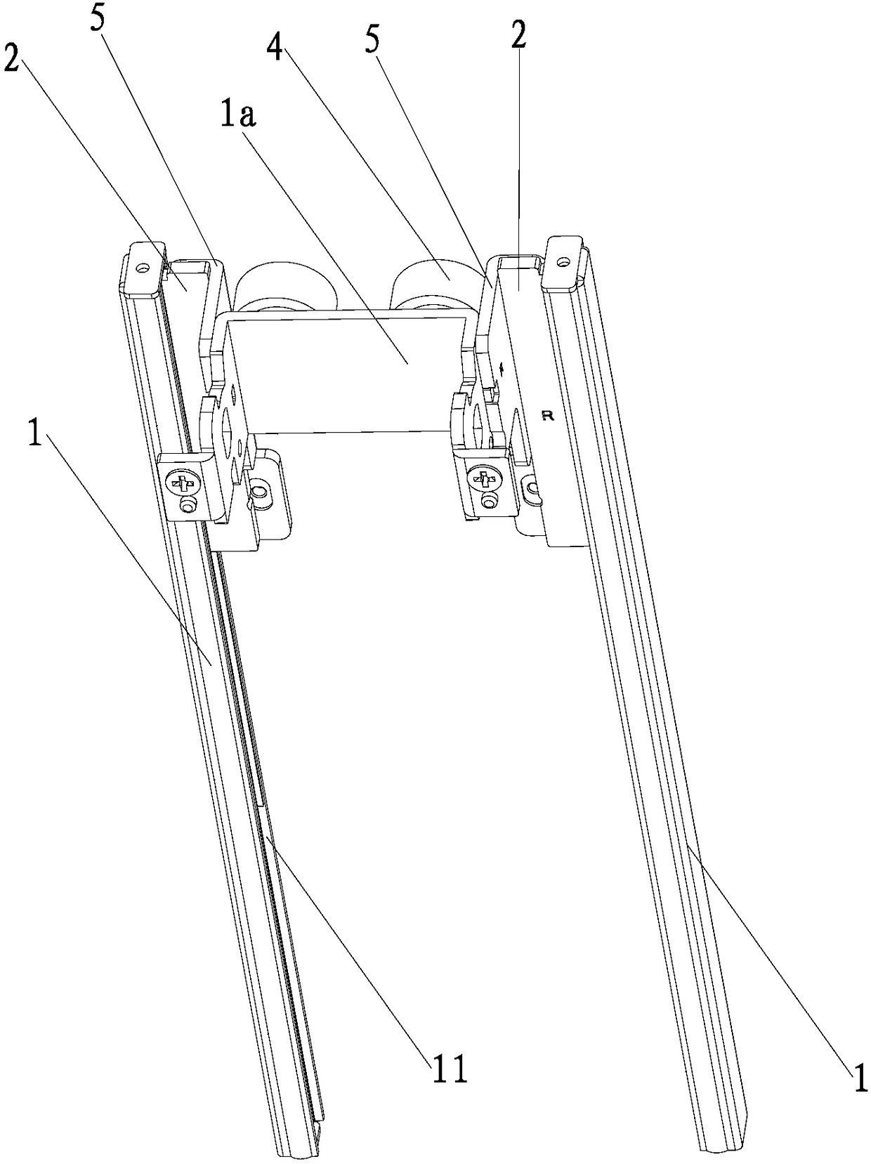
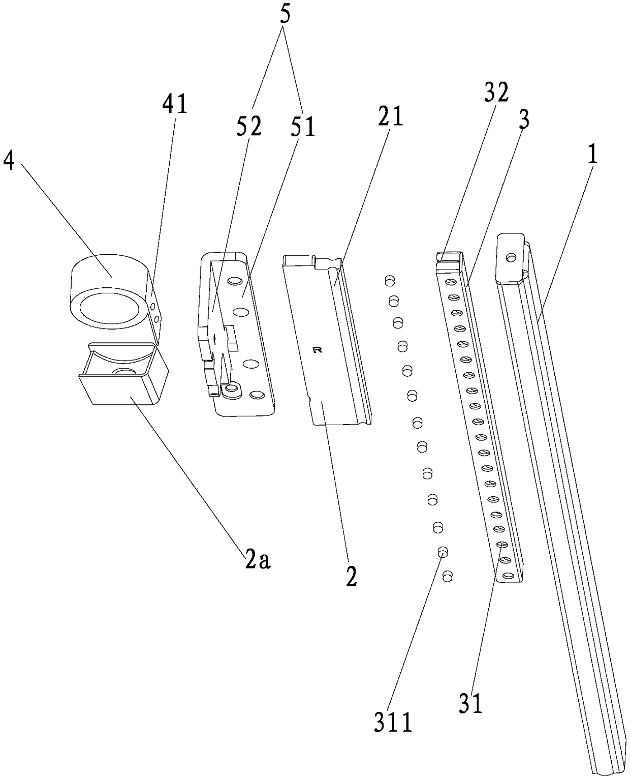
[0026] A lifting mechanism for ultra-thin monitor stand, such as figure 1 As shown, it includes a slide rail body 1, a lifting body 2, a ball cage 3 and a constant force spring 4. The slide rail body 1 is in the shape of a flat box, and the slide rail body 1 is provided with a receiving groove 11 for the ball cage 3 to be embed...


PUM


Abstract

The invention discloses a lifting mechanism for an ultra-thin display bracket. The lifting mechanism comprises sliding rail bodies, lifting bodies, ball retainers and constant force springs; containing grooves allowing the ball retainers to be embedded are formed in the sliding rail bodies; a plurality of balls are arranged on the two opposite side walls of the ball retainers correspondingly; sliding grooves which slidably make contact with the balls on the ball retainers are formed in the two opposite groove walls of the containing grooves correspondingly; each lifting body is in a plate shape; inserting grooves allowing one sides of the lifting bodies to be inserted are formed in the ball retainers; guiding grooves are symmetrically formed in the two opposite end faces of the sides, inserted into the ball retainers, of the lifting bodies correspondingly, and the guiding grooves also slidably make contact with the balls on the ball retainers; and the constant force springs are arranged on the other sides of the lifting bodies, and the movable end of each constant force spring is connected with the corresponding lifting body together through a connecting plate. According to the lifting mechanism for the ultra-thin display bracket, compared with the prior art, the structure thickness is small, and the lifting mechanism can be applied to the ultra-thin display bracket.

Description

technical field [0001] The invention relates to the technical field of display auxiliary equipment, in particular to a lifting mechanism for an ultra-thin display stand. Background technique [0002] Due to the characteristics of smooth movement and stable structure, ball-type slide rails (slide rails can also be called guide rails) are widely used in server cabinets, display brackets, and sliding frames for other electronic products. [0003] Chinese utility model patent (authorized notification number is CN201237068Y) discloses a lifting mechanism for a display stand, which includes a track vertically arranged on the display stand, a lifting body that slides along the track and is fixedly connected with the display, and is fixedly embedded in the lifting body. The friction plate on and in frictional contact with the track, one end connected with the lifting body and used to balance the weight of the display, the friction plate is provided with a first square groove on the ...

Claims


Application Information

Patent Timeline
Patent Type & Authority Applications(China)
IPC IPC(8): F16M11/04F16C29/04
CPCF16C29/005F16C29/04F16M11/046F16M2200/047
Inventor 苏文露林海斌陈建和汪辉
Owner FUJIAN RICHES ELECTRONICS SCI & TECH
Learn More