Open hydraulic fluid flow circuit arrangement and method of controlling the hydraulic circuit

A fluid flow and fluid technology, applied in the field of electronic control devices, can solve problems such as mechanical brake wear and low energy efficiency

Active Publication Date: 2018-05-29
DANFOSS POWER SOLUTIONS GMBH & CO
View PDF11 Cites 0 Cited by
  • Summary
  • Abstract
  • Description
  • Claims
  • Application Information

AI Technical Summary

Problems solved by technology

However, it is quite obvious that this is disadvantageous not only due to the wear of the mechanical brakes, but also due to the lower energy efficiency of the vehicle

Method used


Image

  • Open hydraulic fluid flow circuit arrangement and method of controlling the hydraulic circuit
  • Open hydraulic fluid flow circuit arrangement and method of controlling the hydraulic circuit
  • Open hydraulic fluid flow circuit arrangement and method of controlling the hydraulic circuit

Examples


Embodiment Construction

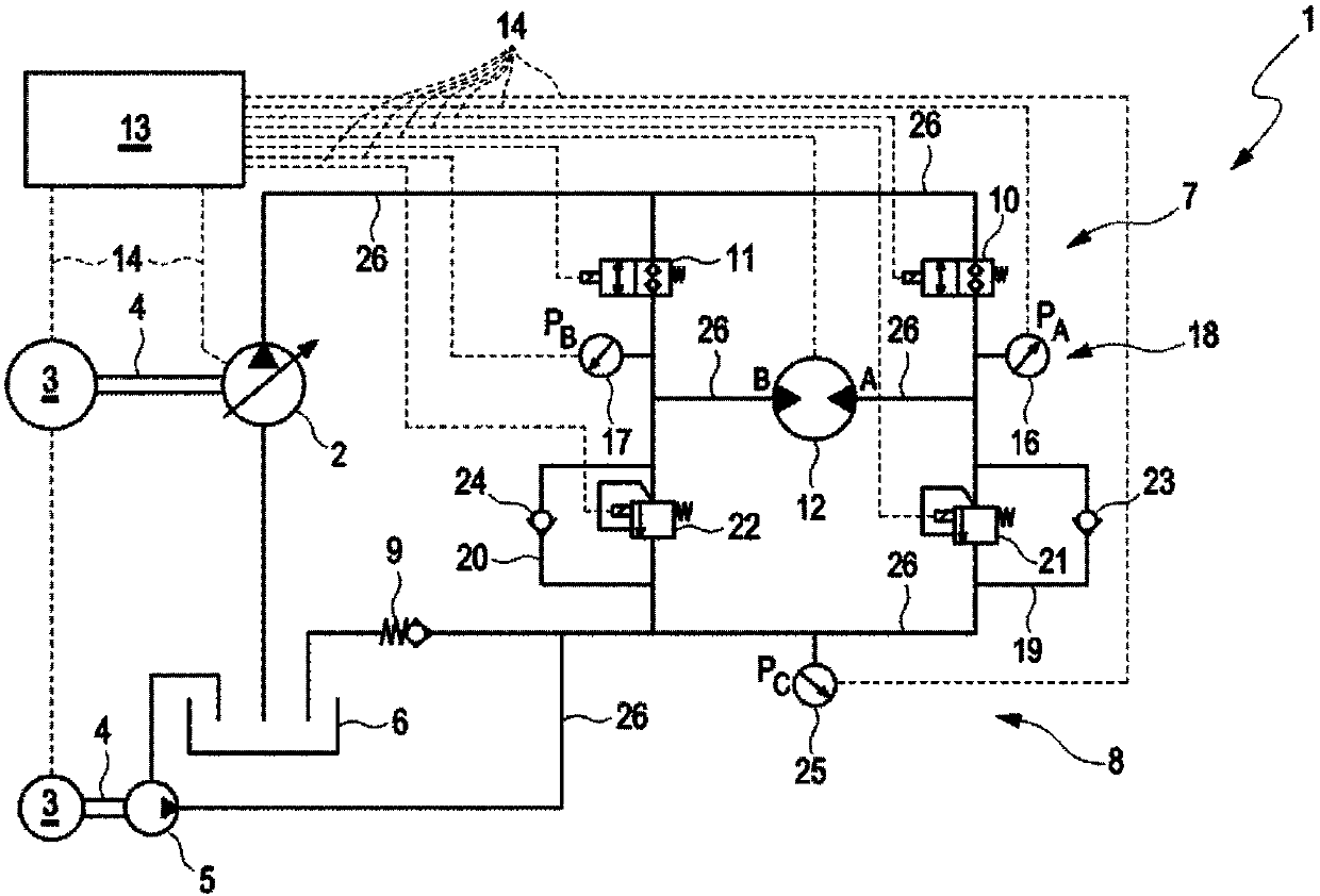
[0034] exist figure 1 In, a first embodiment of a hydraulic propulsion circuit 1 that can be used in mobile vehicles (especially vehicles that use hydraulic systems anyway, for example, forklifts, shovel loaders, excavators, etc.) is shown as a fluid Flow diagram. The presently shown hydraulic propulsion circuit 1 is set up in such a way that the vehicle can be moved in two different (opposite) directions, ie in forward and reverse directions. Since the diagram is set in a symmetrical manner, the propulsion characteristics (maximum speed, torque, etc.) are essentially the same in both directions. This is actually the preferred behavior for machinery such as excavators or forklifts. Furthermore, it can be seen that the hydraulic propulsion circuit 1 is of the open hydraulic fluid flow circuit type.

[0035] In "real life" the output of the main hydraulic pump 2 could also be used for different purposes, like hydraulic pistons for raising the forks of a forklift, hydraulic pi...


PUM


Abstract

The invention relates to a fluid flow arrangement (1, 15) with an adjustable fluid pumping device (2) and a fluid working machine (12). The fluid working machine (12) is connected to the fluid pumpingdevice (2) and a re-circulating loop is provided for the fluid working machine (12). The re-circulating loop is fluidly connecting a first fluid port (A) and a second fluid port (B) of the fluid working machine (12), where the first (A) and the second fluid port (B) are at times at a different pressure level. The re-circulating loop comprises a controllable fluid throttling device (21, 22), and aswitchable fluid conduit device (23, 24), so that a defined decelerating force can be generated for the fluid working machine (12).

Description

field of invention [0001] The present invention relates to a fluid flow device comprising an adjustable fluid pumping device and a fluid working machine fluidly connected to the fluid pumping device, and further comprising a reconfiguration of the first fluid port and the second fluid port fluidly connected to the fluid working machine A circulation loop wherein the first fluid port and the second fluid port are sometimes at different pressure levels. The invention also relates to an electronic control arrangement for such a fluid flow device (or similar arrangement). Background technique [0002] Hydraulic transmissions for the transfer of mechanical energy from one place to another are used in several technical fields at the same time (often involving the possibility of changing some characteristics of the mechanical energy involved, such as rotational speed, possible torque, etc.). An example of this is the field of wind power generators, where due to varying wind speeds...

Claims


Application Information

Patent Timeline
Patent Type & Authority Applications(China)
IPC IPC(8): F15B13/02F15B19/00F15B21/02
CPCF15B13/02F15B13/027F15B19/00F15B21/02F15B2211/30525F15B2211/6306F16H61/4157F16H61/4148F16H61/4017
Inventor 弗罗伦·林丁格斯文·佛英克
Owner DANFOSS POWER SOLUTIONS GMBH & CO
Why Eureka
Try Eureka