
Cleaning device for inner walls of steel pipes

A cleaning device and a technology for the inner wall of a steel pipe, applied in the direction of cleaning hollow objects, cleaning methods and utensils, chemical instruments and methods, etc., to achieve the effect of power source energy saving and high-quality cleaning

Pending Publication Date: 2018-05-29
江苏博隆锦欣环保设备有限公司
View PDF0 Cites 14 Cited by
  • Summary
  • Abstract
  • Description
  • Claims
  • Application Information

AI Technical Summary

Problems solved by technology

[0006] The technical problem to be solved by the present invention is: to overcome the deficiencies of the prior art, to provide a cleaning device for the inner wall of the steel pipe, and to solve the defect that the water flow cannot be used for moving and cleaning in the pipe in the past

Method used


Image

  • Cleaning device for inner walls of steel pipes
  • Cleaning device for inner walls of steel pipes
  • Cleaning device for inner walls of steel pipes

Examples


Embodiment Construction

[0031] The present invention will be further described in conjunction with specific embodiment now. These drawings are simplified schematic diagrams only to illustrate the basic structure of the present invention in a schematic way, so they only show the components relevant to the present invention.

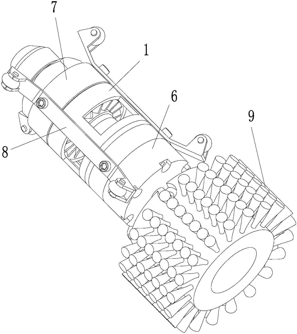
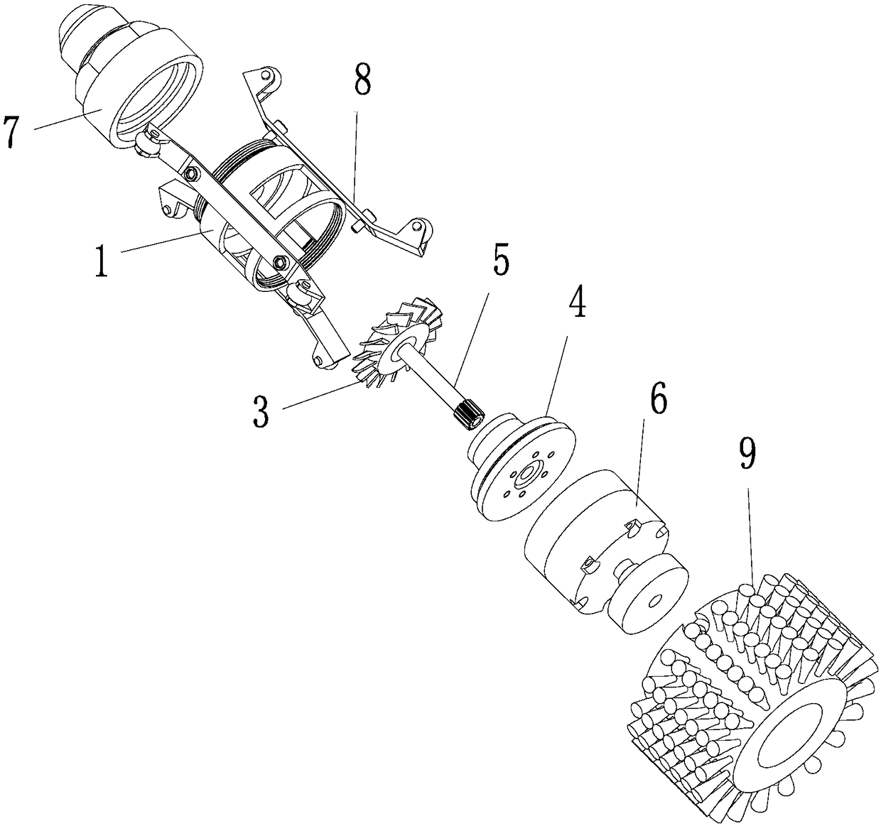
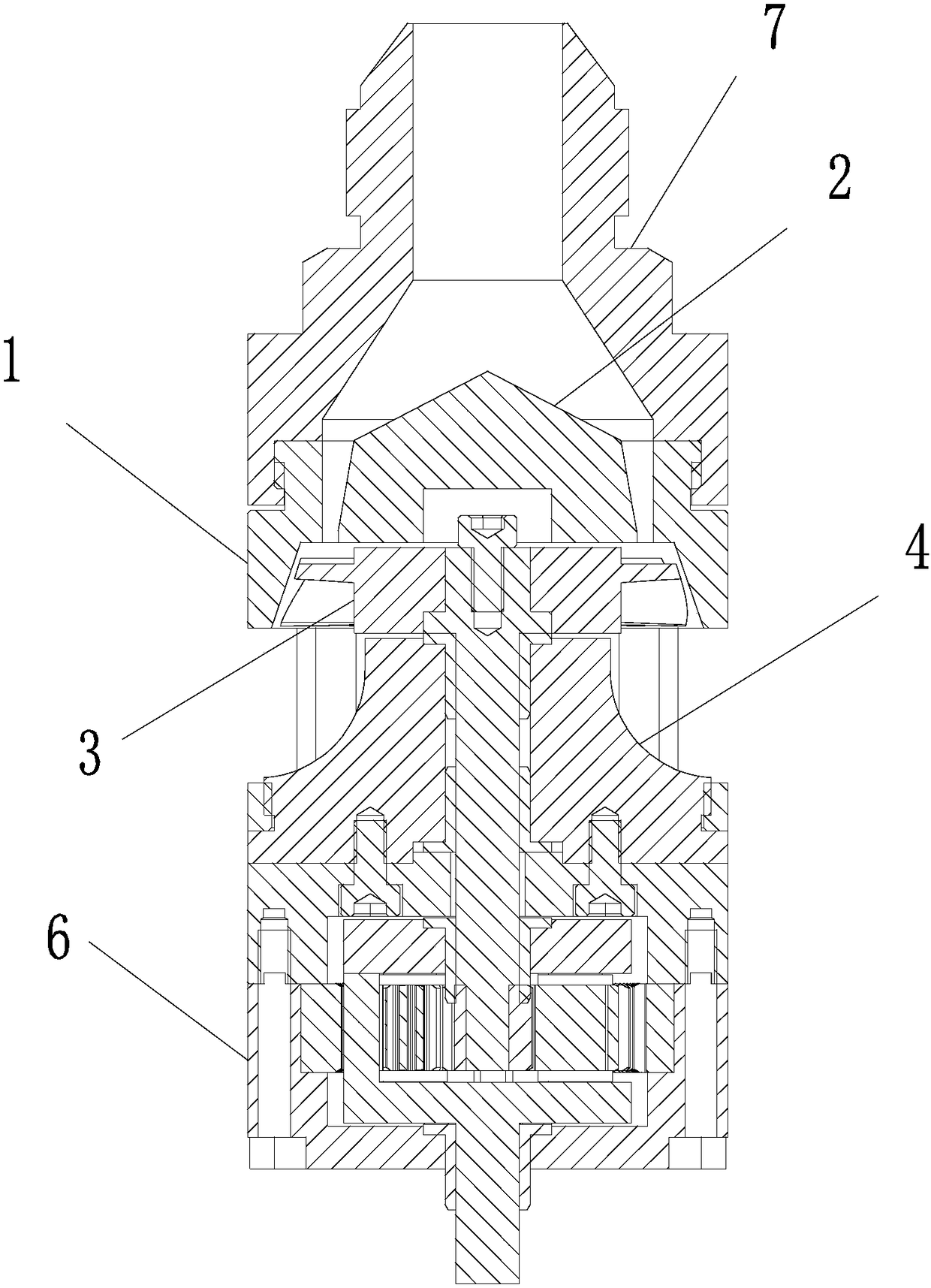
[0032] like Figure 1 to Figure 8 As shown, a cleaning device for the inner wall of a steel pipe includes a casing 1, and the casing 1 is sequentially provided with a first installation chamber, an impeller chamber 1B and a second installation chamber from top to bottom, and a shunt is fixedly arranged in the first installation chamber. Part 2, a water inlet ring cavity 1A is formed between the surroundings of the distribution part 2 and the inner wall of the first installation cavity, and the water inlet ring cavity 1A communicates with the impeller cavity 1B. The flow guide 4 is fixedly arranged at the lower end of the housing 1, the flow guide 4 is located in the second insta...


PUM


Abstract

The invention relates to a cleaning device for inner walls of steel pipes. The cleaning device comprises a shell; a first mounting cavity, an impeller cavity and a second mounting cavity are arrangedin the shell in sequence from top to bottom; a flow separation piece is fixedly arranged in the first mounting cavity; a water inlet ring cavity is formed between the periphery of the flow separationpiece and the inner wall of the first mounting cavity, and communicates with the impeller cavity; a guide piece is fixedly arranged at the lower end of the shell, and is positioned in the second mounting cavity; a guide cavity is formed between the periphery of the guide piece and the inner wall of the second mounting cavity, and communicates with the impeller cavity; water leakage ports are formed in the shell around the guide cavity; a rotatable impeller is arranged in the impeller cavity, and is connected with a rotating shaft; and the lower end of the rotating shaft penetrates through theguide piece to form a torsion output end. The cleaning device can move in pipes for cleaning; the source of working power of the whole cleaning device depends on impact force of water currents introduced into the cleaning device, so that the power source of the cleaning device is more energy-saved and environment-friendly; and the cleaning device cleans in pipes fully filled with water, and realizes high-quality cleaning of the inner walls of the pipes.

Description

technical field [0001] The invention relates to a cleaning device for the inner wall of a steel pipe. Background technique [0002] The degreasing process in the production process of stainless steel pipe is generally carried out before the heat treatment or inspection process to prepare for the heat treatment and inspection process of the steel pipe. The degreasing process is one of the important processes in the stainless steel pipe production process. In the production of stainless steel pipes, if the degreasing process is not in place, the steel pipes with lubricant oil on the surface enter the bright continuous treatment furnace for heat treatment, which will lead to the following two results: (1) The surface of the stainless steel pipe after heat treatment will appear "yin "color" (carburization), which reduces its intergranular corrosion resistance, especially for ultra-low carbon stainless steel pipes; (2) destroys the atmosphere in the furnace for protecting the br...

Claims


Application Information

Patent Timeline
IPC IPC(8): B08B9/055
CPCB08B9/0553
Inventor 徐达明徐建灵刘贤伟唐建忠
Owner 江苏博隆锦欣环保设备有限公司
Learn More