
Motor

A motor and iron core technology, applied in the field of motors, can solve the problems such as the deterioration of the roundness of the inner peripheral surface of the iron core cage, the inability to install heat sinks, and the increase of cogging torque, so as to suppress the deterioration of the roundness and achieve good rigidity. , the effect of reducing cogging torque

Active Publication Date: 2018-05-25
SANKYO SEIKI MFG CO LTD
View PDF5 Cites 0 Cited by
  • Summary
  • Abstract
  • Description
  • Claims
  • Application Information

AI Technical Summary

Problems solved by technology

However, when one of the four sides is provided with a lead wire extraction portion, it is not possible to provide a heat sink on the surface provided with the lead wire extraction portion in the same manner as the other surfaces.
Therefore, the wall thickness and cross-sectional shape of the core cage on only one side are different from those on the other sides, so the deformation due to the stress generated during shrink fitting becomes large.
As a result, the roundness of the inner peripheral surface of the core holder deteriorates and the cogging torque may increase.

Method used


Image

  • Motor
  • Motor
  • Motor

Examples


Embodiment Construction

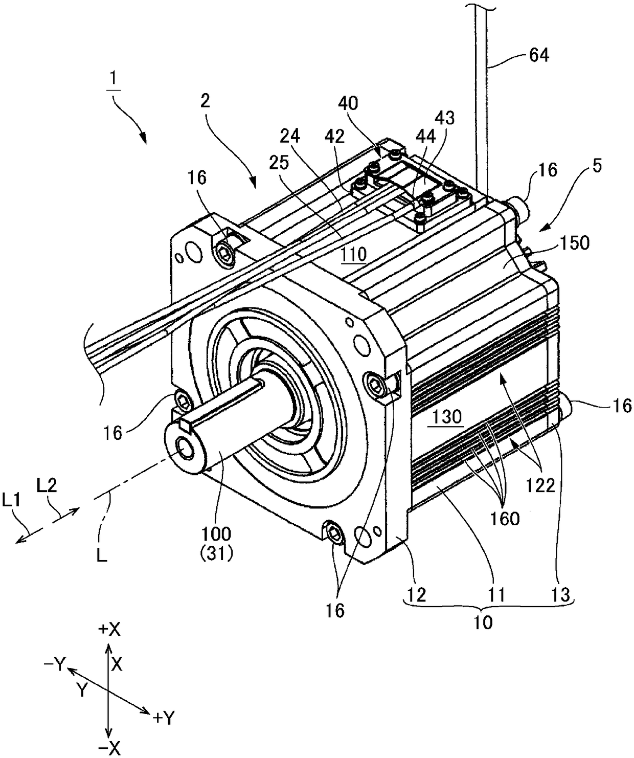
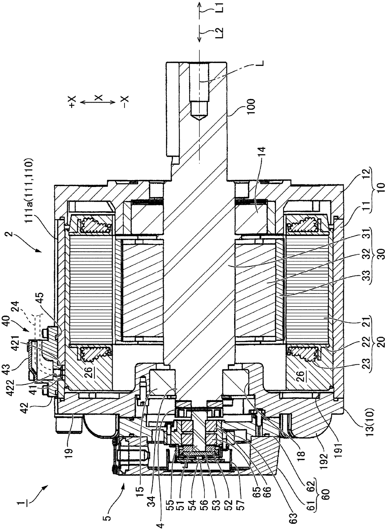
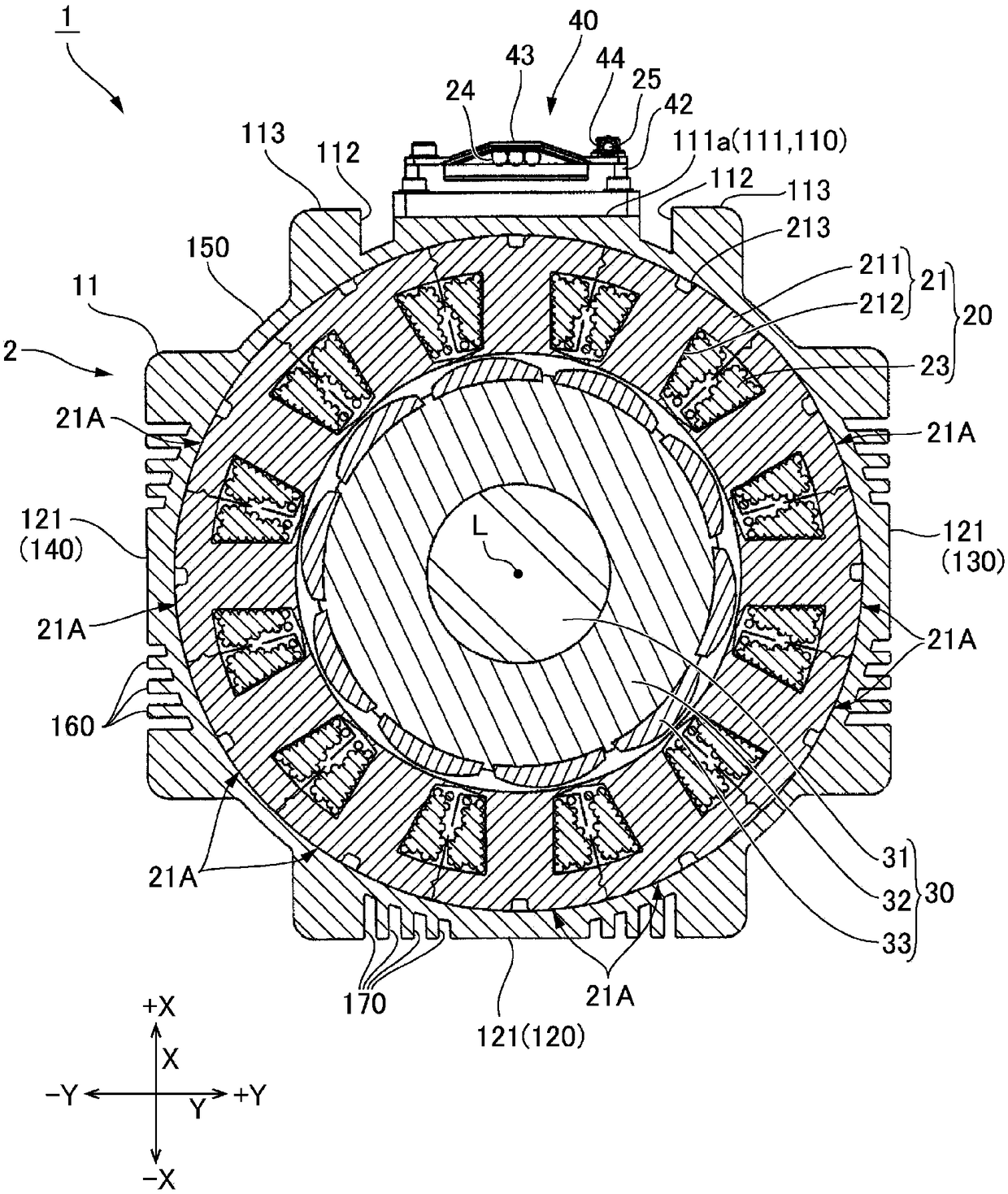
[0030] Embodiments of a motor to which the present invention is applied will be described below with reference to the drawings. figure 1 is an external perspective view of the motor 1 according to the present invention viewed from the output side, figure 2 This is a cross-sectional view obtained by cutting the motor 1 along a plane parallel to the axial direction L. As shown in FIG. and, image 3 This is a cross-sectional view obtained by cutting the motor 1 along a plane perpendicular to the axial direction L. As shown in FIG. In this specification, the side where the output shaft 100 of the motor 1 protrudes out of the one side and the other side in the axial direction L of the motor 1 is referred to as the output side L1, and the side opposite to the side where the output shaft 100 protrudes is referred to as the output side L1. Output the opposite side L2. In addition, two directions perpendicular to the axial direction L are defined as the X direction and the Y direct...


PUM


Abstract

The present invention provides a motor capable of providing a wire take-out portion (40) on the outer peripheral surface of a core holder (11), and suppressing deformation due to shrink fit of a stator core (21) to suppress the increase of cogging torque. In the motor (1) with an encoder, the stator core (21) is fixed inside the core holder (11) by shrink fit. The outer circumferential surface ofthe core holder (11) has a rectangular tube shape, and a first flat portion (111) for fixing the wire holder (42) is provided on the side surface (110). The other side surfaces (120, 130, 140) includea heat dissipation portion (122) formed by alternately arranging the heat dissipation fins (160) and the groove portions (170). Recesses (112) are formed on both sides in the width direction of the first flat portion (111) of the side surface (110). In addition, the upper end surface (111a) of the first flat portion (111) is lower by one layer, and the wall thickness (t4) of the first flat portion (111) is less than the wall thickness of the second flat portion (121) provided at the other side surfaces (t5).

Description

technical field [0001] The present invention relates to a motor in which a stator core is fixed on the inner periphery of a motor casing. Background technique [0002] Conventionally, in a motor using a laminated core formed by laminating thin steel plates as a stator core, the stator core is fixed to the inner periphery of the cylindrical portion (core holder) of the motor case. , using the method of pressing the stator core into the core cage. Or use the following method (shrink fitting): Put the core holder on the stator core while expanding the inner diameter of the core holder through thermal expansion, then let the core holder cool and shrink, and pass the iron core holder from the outer peripheral side. The core holder fastens and fixes the stator core. Patent Document 1 discloses a motor (servo motor) in which a stator core is fixed to a core holder by shrink fitting. [0003] In the case where the stator core is fixed to the core holder by shrinkage, adverse effe...

Claims


Application Information

Patent Timeline
Patent Type & Authority Applications(China)
IPC IPC(8): H02K3/52H02K1/20
CPCH02K1/20H02K3/522
Inventor 松村修太
Owner SANKYO SEIKI MFG CO LTD
Learn More