
Straw compressing device providing convenience for subsequent utilization of straws

A compression device and straw technology, applied in the field of compression equipment, can solve the problems of low efficiency, scattered straw, inconvenient use, etc., and achieve the effect of follow-up utilization, high void ratio, and easy production

Inactive Publication Date: 2018-05-25
ZHENGZHOU QISHUO ELECTRONICS TECH CO LTD
View PDF0 Cites 0 Cited by
  • Summary
  • Abstract
  • Description
  • Claims
  • Application Information

AI Technical Summary

Problems solved by technology

In order to use the straw in the future, it is necessary to compress the straw reasonably. The existing straw compressor (also called a straw briquetting machine) exerts a very large pressure on the straw, and the final compressed straw is very compact. However, in In the subsequent use of straw, such as the use of straw returning to the field, machinery, silage processing, and papermaking, the compression method of straw is to use no crushing, and then directly compress the straw. The existing compression device can only be used for The straw produces a large pressure, and the pores in the compressed straw are very small, which is not conducive to the fermentation of microorganisms; but if the compression is not performed properly, the accumulation and transportation of the straw are not convenient. For a slightly compressed device, if no compression is performed at all, the straw will be scattered, inconvenient for transportation and arrangement, and even more inconvenient for subsequent use. Therefore, a device that can make the straw have a regular shape is needed; and the traditional compression mechanism is huge. When the straw is compressed, it can only be compressed from one direction, for example, it can only be compressed horizontally or vertically, and the straw cannot be compressed in two directions or even three directions at the same time, resulting in low compression efficiency

Method used


Image

  • Straw compressing device providing convenience for subsequent utilization of straws
  • Straw compressing device providing convenience for subsequent utilization of straws
  • Straw compressing device providing convenience for subsequent utilization of straws

Examples


Embodiment Construction

[0016] The technical solution in this embodiment will be clearly and completely described below in conjunction with the accompanying drawings in the embodiment of the present invention. Obviously, the described embodiment is only a part of the embodiments of the present invention, not all of the embodiments. Based on the embodiments of the present invention, all other embodiments obtained by persons of ordinary skill in the art without making creative efforts belong to the protection scope of the present invention.

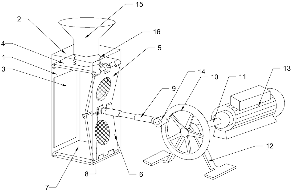
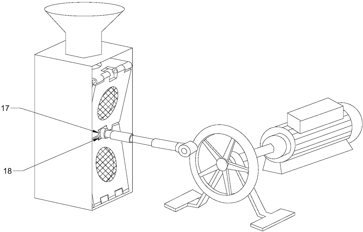
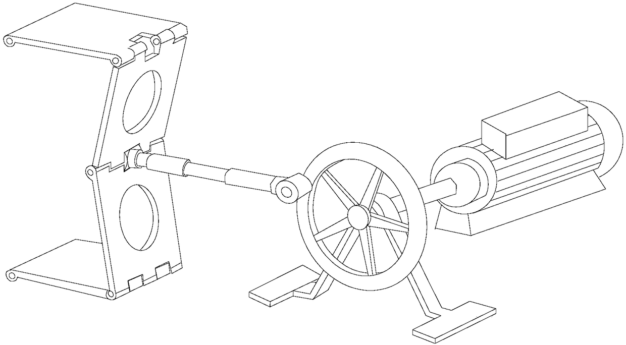
[0017] Such as Figure 1-3 as shown, figure 1 In , for the convenience of seeing the internal structure clearly, it should be understood that the internal structure is directly drawn without dotted lines. The straw compression device of this embodiment, which is convenient for the subsequent utilization of straw, includes a casing, a compression device and a compression drive device. The baffle, the front baffle 1 is provided with a door panel 3 for putting in a...


PUM


Abstract

The invention discloses a straw compressing device providing convenience for subsequent utilization of straws and relates to the field of compression equipment. The straw compressing device comprisesa shell, a compressing device part and a compression driving device; the shell is a rectangular shell and comprises a front baffle, a left baffle, a right baffle, an upper baffle and a lower baffle; the compressing device part is positioned inside the shell and comprises an upper compressing plate, a first side surface compressing plate, a second side surface compressing plate and a lower compressing plate which are articulated in sequence; the upper compressing plate and the lower compressing plate are both parallel to the upper baffle and the lower baffle; a supporting rod which can be takenout randomly is arranged between the upper compressing plate and the lower compressing plate; a rotary cylinder is arranged at the joint of the first side surface compressing plate and the second side surface compressing plate; the rotary cylinder is connected with a telescopic rod; and the telescopic rod is positioned outside the shell. The straw compressing device disclosed by the invention applies a small compression force on the straws so that the straws have a high void ratio, and the straws are not compressed too compactly, so convenience is provided for subsequent utilization of the straws.

Description

technical field [0001] The invention relates to the field of compression equipment, in particular to a straw compression device that facilitates the subsequent utilization of straw. Background technique [0002] Since the gradual promotion of large-scale combine harvesters, the main way for farmers to dispose of straw has been to directly burn it in the field, polluting the atmosphere, or filling it into the ditch and river beside the field, making the ditch black and smelly, the fish and shrimp disappeared, and the groundwater Serious pollution threatens the safety of drinking water for farmers. Therefore, the rational use of straw can reduce environmental pollution while turning waste into wealth and provide energy for families. There are many uses of straw, generally including five Major categories: first, as farm fertilizers, including rice field conservation tillage, mechanical straw returning, composting and retting, and the use of biotechnology to ferment biological f...

Claims


Application Information

Patent Timeline
Patent Type & Authority Applications(China)
IPC IPC(8): B30B9/30
CPCB30B9/3003B30B9/3021B30B9/305B30B9/306
Inventor 高翔
Owner ZHENGZHOU QISHUO ELECTRONICS TECH CO LTD
Learn More