
Valve needle drive cylinder and needle valve type hot runner system

A technology of drive cylinder and valve needle, which is applied in the field of hot runner injection molding, can solve the problems of unstable linkage, low strength of pin 40', and difficult processing, so as to improve work stability, reduce production cost, and save process timeliness.

Inactive Publication Date: 2018-05-25
YUDO SUZHOU HOT RUNNER SYST
View PDF2 Cites 0 Cited by
  • Summary
  • Abstract
  • Description
  • Claims
  • Application Information

AI Technical Summary

Problems solved by technology

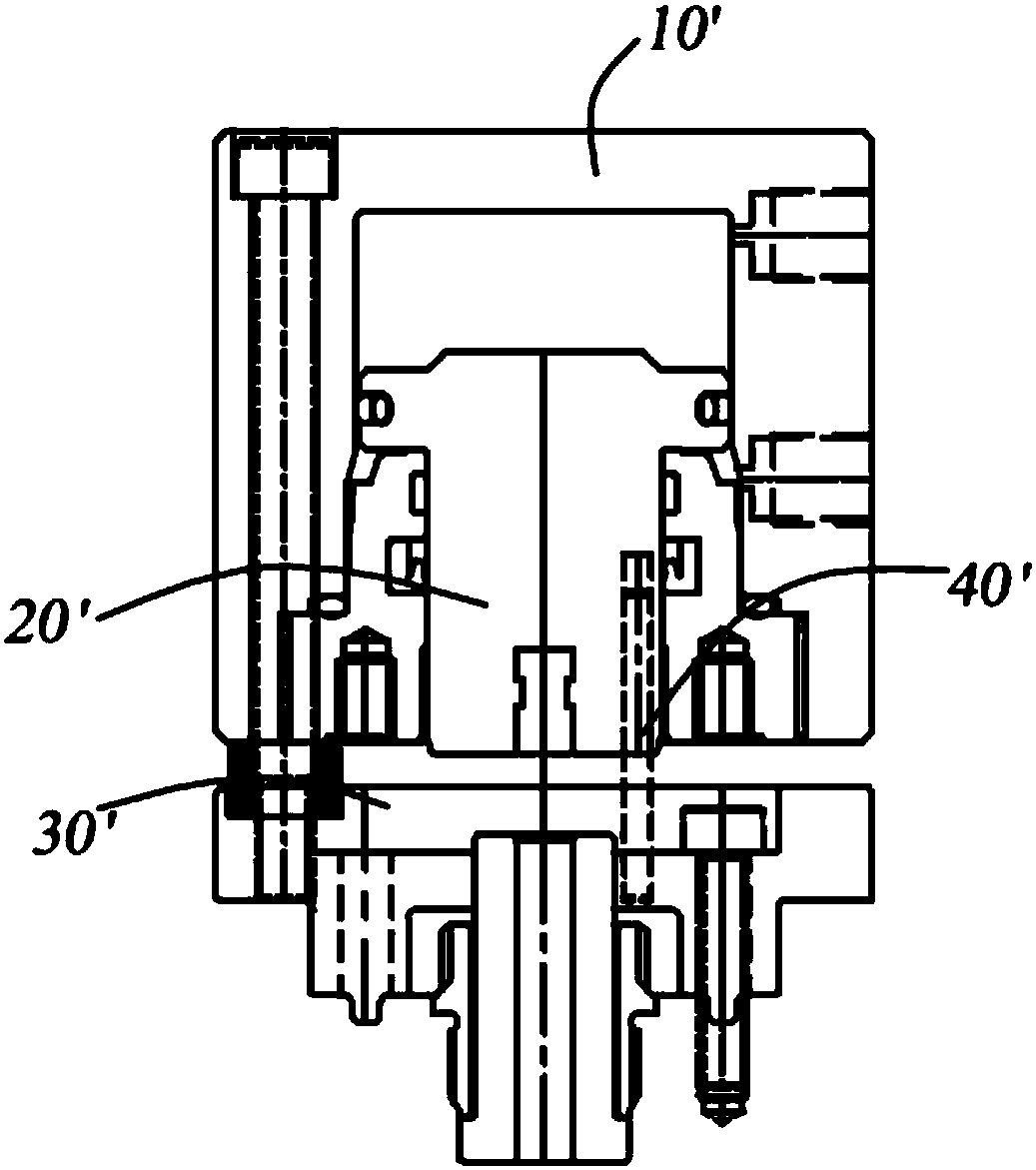
However, the pin 40' needs to be connected to the bottom of the cooling water circuit board 30' and the piston 20'. Since the cooling water circuit board 30' is fixed with the diverter plate, when the piston 20' and the pin 40' are fixed with the cooling water circuit board 30', it is easy to Unbalanced driving occurs, and because the space on the lower side of the piston 20' is small, the processing is difficult, resulting in the strength of the pin 40' being too small, so that there is instability when the entire system is linked, and the piston cannot stop without a cooling water circuit board

Method used


Image

  • Valve needle drive cylinder and needle valve type hot runner system
  • Valve needle drive cylinder and needle valve type hot runner system
  • Valve needle drive cylinder and needle valve type hot runner system

Examples


Embodiment Construction

[0029] The present invention will be described in detail below with reference to the specific embodiments shown in the accompanying drawings. However, these embodiments do not limit the present invention, and structural, method, or functional changes made by those skilled in the art according to these embodiments are all included in the protection scope of the present invention.

[0030] In the various figures of the present invention, some dimensions of structures or parts are exaggerated relative to other structures or parts for convenience of illustration, and thus are only used to illustrate the basic structure of the subject matter of the present invention.

[0031] Terms such as "upper," "over," "lower," "below," and the like, referring to spatially relative positions, are used herein for ease of illustration to describe one element or feature relative to another as shown in the figures The relationship of a unit or feature. The term spatially relative position may be i...


PUM


Abstract

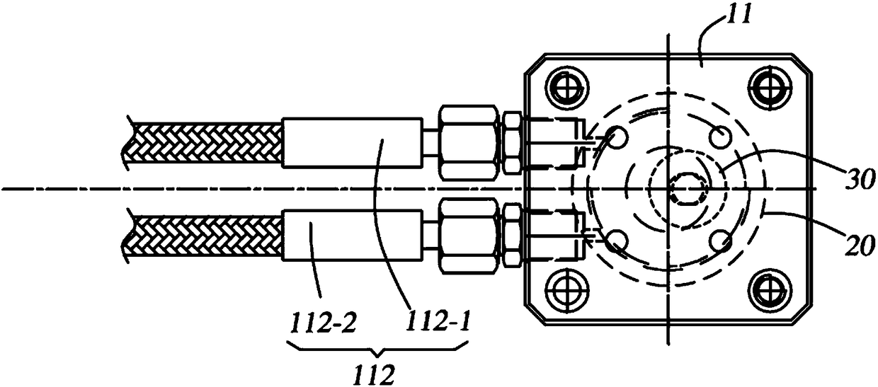
The invention discloses a valve needle drive cylinder and a needle valve type hot runner system. The valve needle drive cylinder comprises a cylinder body and a piston located in the cylinder body; avalve needle hanging table used for fixed mounting of a valve needle is arranged below the piston, and the cylinder is characterized in that a pin is arranged at the position, on the non-axis positionof the piston, between the piston and the cylinder body, in the piston work process, piston rotation stop is achieved, two ends of the pin are mounted in a manner of being matched with the cylinder body and the piston, one end of the pin is movably mounted along the axis of the pin, and guidance is achieved in the piston moving process. Positioning is achieved without an outer structure, mountingspace of the rotation stop structure in the cylinder body is reduced, production cost is reduced, the assembling strength between the cylinder body and the piston is improved, work stability of the valve needle drive cylinder is improved, and process time is saved.

Description

technical field [0001] The invention belongs to the technical field of hot runner injection molding, and particularly relates to a valve needle drive cylinder and a needle valve type hot runner system. Background technique [0002] A hot runner is a collection of heating components used in injection molds to inject molten plastic into the cavity of the mold. The hot runner system is generally composed of hot nozzles, manifolds, temperature control boxes and accessories. The hot runner system is divided into an open hot runner system and a needle valve hot runner system. According to the raw materials, appearance, and performance requirements of different products, the corresponding hot runner system that meets the requirements is selected, and the corresponding nozzle form is selected. [0003] A hot runner is a collection of heating components used in injection molds to inject molten plastic into the cavity of the mold. The hot runner system is generally composed of hot n...

Claims


Application Information

Patent Timeline
IPC IPC(8): B29C45/28
CPCB29C45/281B29C2045/2827
Inventor 李象烈
Owner YUDO SUZHOU HOT RUNNER SYST
Learn More