Optical rapid compression machine combustion cylinder capable of realizing shooting by schlieren method

A technology of combustion cylinder and schlieren method, applied in combustion engine, mechanical equipment, internal combustion engine testing and other directions, can solve the problem of difficult to adapt to the schlieren method optical path layout, and achieve the effect of reducing material consumption, optimizing structural design, and improving accuracy

Active Publication Date: 2018-05-22
TIANJIN UNIV
View PDF6 Cites 6 Cited by
  • Summary
  • Abstract
  • Description
  • Claims
  • Application Information

AI Technical Summary

Problems solved by technology

In order to realize the visual research on the interaction between the flame and the shock wave by using the fast compressor, it is necessary to use the schlieren method to photograph the combustion process in the cylinder, but the optical windows of the existing fast compressor platform are mostly arranged on the top of the combustion cylinder and the piston In the plane where the movement direction is vertical, it is mainly used to realize direct shooting, but it is difficult to adapt to the optical path arrangement of the schlieren method

Method used


Image

  • Optical rapid compression machine combustion cylinder capable of realizing shooting by schlieren method
  • Optical rapid compression machine combustion cylinder capable of realizing shooting by schlieren method
  • Optical rapid compression machine combustion cylinder capable of realizing shooting by schlieren method

Examples


Embodiment Construction

[0026] The technical solution of the present invention will be further described in detail below in conjunction with the accompanying drawings and specific embodiments, and the described specific embodiments are only for explaining the present invention, and are not intended to limit the present invention.

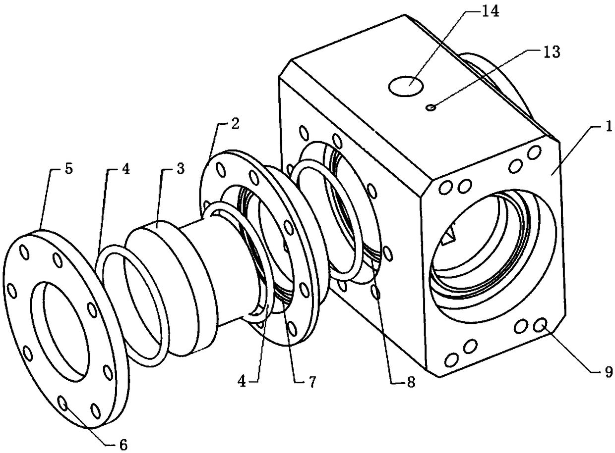
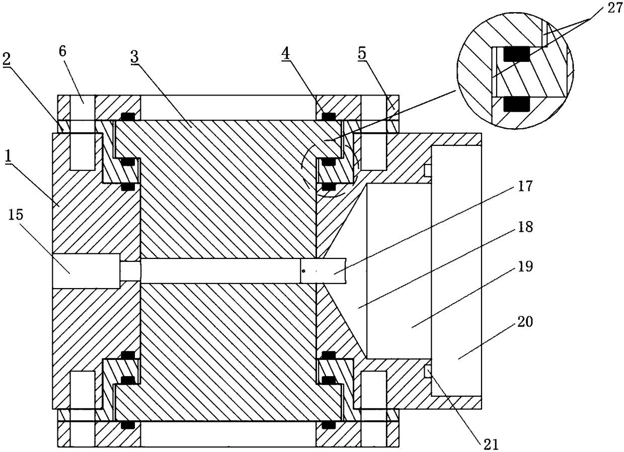
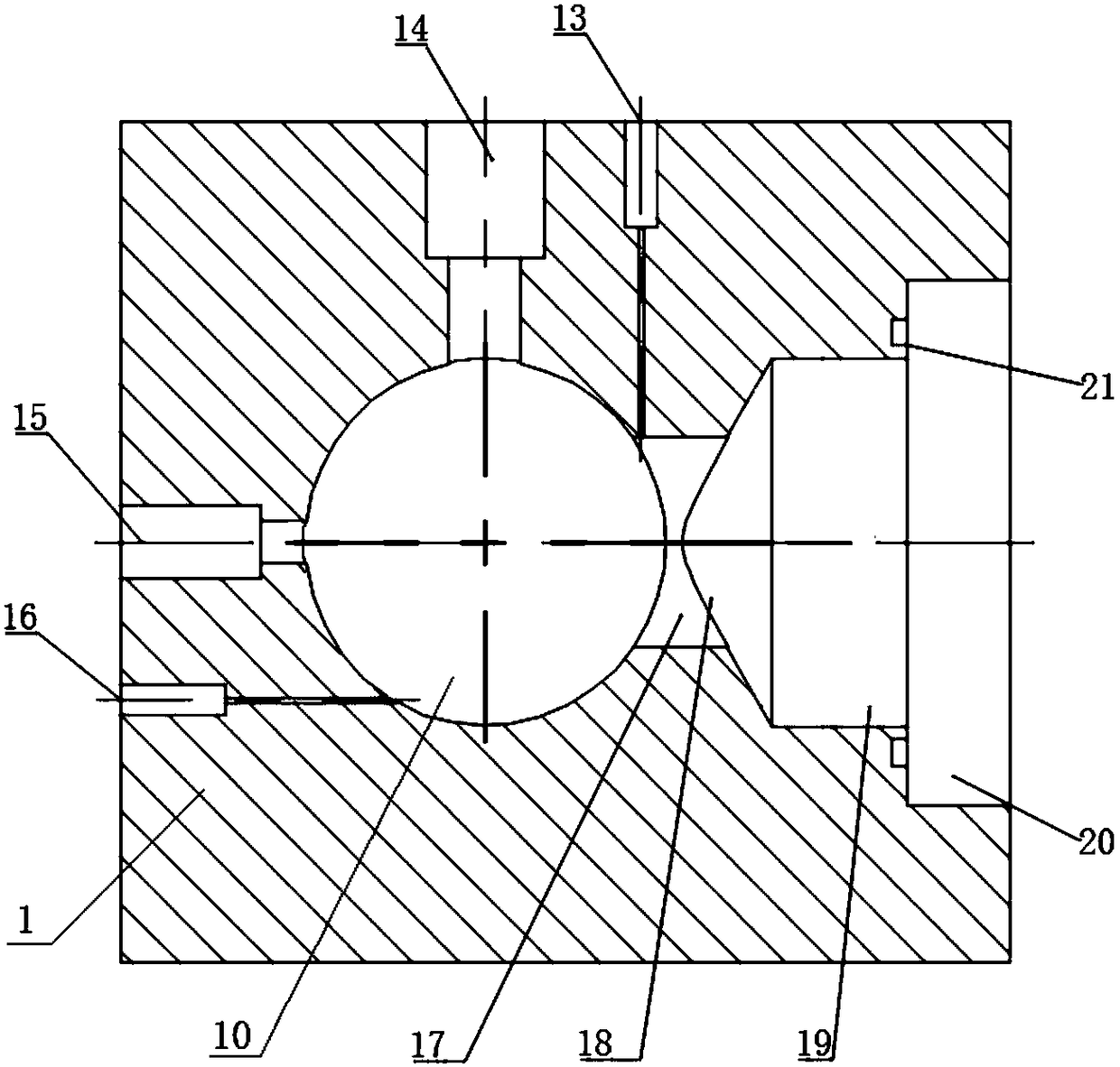
[0027] like Figure 1 to Figure 6 As shown, the present invention can realize the optical fast compressor combustion cylinder of schlieren method photographing, comprise combustion cylinder main body 1, the profile of described combustion cylinder main body 1 can be cuboid, and material is No. 45 steel, and the four corners of cuboid all cut off certain In order to reduce the sharpness of its corners, improve the safety of the experiment, and reduce the weight of the combustion cylinder at the same time. A combustion chamber cavity 10 is arranged between the front and rear ends of the combustion cylinder main body 1, and a window positioning cavity 11 is provided at the fr...


PUM


Abstract

The invention discloses an optical rapid compression machine combustion cylinder capable of realizing shooting by a schlieren method. A combustion chamber cavity penetrates through the front end faceand the rear end face of a combustion cylinder body; the front end and the rear end of the combustion chamber cavity are respectively provided with window locating cavities; the left end face of the combustion cylinder body is provided with a cylinder pressure sensor mounting hole and a vent hole, the upper surface of the combustion cylinder body is provided with a sparking plug mounting hole andan air inlet, and the right end face of the combustion cylinder body is provided with a combustion cylinder locating cavity; a rectangular channel, a tapered transition section, and a compression section are sequentially arranged between the combustion cylinder locating cavity and the combustion chamber body from left to right; the front end and the rear end of the combustion chamber body are provided with silica glass, and the silica glass is fixed through glass baffles; a combustion chamber is reserved between the two pieces of silica glass; the combustion chamber communicates with the cylinder pressure sensor mounting hole, the vent hole, the rectangular channel, and the sparking plug mounting hole, and the rectangular channel communicates with the air inlet. The optical rapid compression machine combustion cylinder capable of realizing shooting by the schlieren method mainly changes the direction of the combustion chamber axis, so that the combustion chamber axis is perpendicular to the movement direction of a piston, and the requirements of the optical arrangement of the schlieren method are met.

Description

technical field [0001] The invention belongs to the design field of a fast compressor experiment platform, and relates to a combustion cylinder applied to an optical fast compressor experiment platform, and more specifically relates to a combustion cylinder of an optical fast compressor that can realize schlieren shooting. Background technique [0002] As one of the most important power machines for human activities, the engine consumes a lot of energy and causes serious environmental pollution. In order to further improve the power, economy and emissions of internal combustion engines, engine downsizing has become a mainstream technical means. However, engine knock has become a bottleneck limiting further enhancement of the engine. Knocking will lead to a decline in the thermal efficiency of gasoline engines, accompanied by strong fluctuations in cylinder pressure, and even cause irreversible damage to the engine in severe cases. Therefore, it is urgent to carry out in-de...

Claims


Application Information

Patent Timeline
IPC IPC(8): F02B23/08G01M15/04
CPCF02B23/08G01M15/04Y02T10/12
Inventor 卫海桥张晓军商艺宝张鹏飞
Owner TIANJIN UNIV
Why Eureka
Try Eureka