Al technical title is built by PatSnap Al team. It summarizes the technical point description of the patent document.
A tin dipping machine, fully automatic technology, applied in the field of tin dipping machine, can solve the problems of heavy workload, labor-intensive, troublesome operation of operators, and achieve the effect of increasing storage function, improving efficiency, and being convenient to move.
Pending Publication Date: 2018-05-18
东莞市恒海自动化设备有限公司
View PDF3 Cites 4 Cited by
Summary
Abstract
Description
Claims
Application Information
AI Technical Summary
This helps you quickly interpret patents by identifying the three key elements:
Problems solved by technology
Method used
Benefits of technology
Problems solved by technology
[0002] The structure of the wires used in electronic equipment from the outside to the inside is the protective sheath, the insulating sheath and the core wire. In order to prevent the core wire from being loose after stripping, and to ensure the welding quality between the wire and the electronic components, a certain high Frequency performance, often dip tin at the end of the wire. In the traditional tin dipping process, the usual method is manual operation. Due to the shaking of the hand or the deviation of the line of sight during the manual operation, the end of the wire cannot be leveled. Placed in the tin surface of the tin furnace, this results in different depths of tin dipping at the end of the wire, and it is difficult to guarantee the appearance quality. There are often problems such as bell mouth, bulge, inconsistent tin dipping length, and unstable finished product size. Assembly and other processing and production have brought troubles, poor processing and loss have been significantly increased, and manual tinning is used, the speed of tinning is slow, the operation efficiency is low, the workload of operators is large, and it consumes a lot of manpower, which greatly increases the cost of the enterprise. In response to the above situation, some tin dipping equipment appeared on the market to improve the traditional tin dipping method, but these tin dipping equipment have complex structure, troublesome operation, low tin dipping efficiency, low tin dipping precision, and poor tin dipping quality. At the same time, during the tin dipping process, since the tin water in the tin water tank is prone to solidification, and the tin dipping equipment lacks a certain anti-solidification function, it is necessary to design an automatic wire cutting and tin dipping machine
Method used
Image
Click on the blue label to locate the original text in one second.
Reading with bidirectional positioning of images and text.
Examples
Embodiment Construction
[0016] The technical solutions in the embodiments of the present invention will be clearly and completely described below in conjunction with the accompanying drawings in the embodiments of the present invention. Obviously, the described embodiments are only a part of the embodiments of the present invention, rather than all the embodiments. Based on the embodiments of the present invention, all other embodiments obtained by those of ordinary skill in the art without creative work shall fall within the protection scope of the present invention.
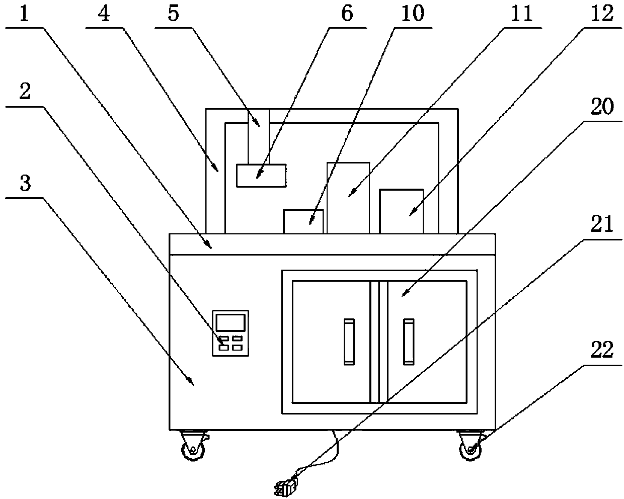
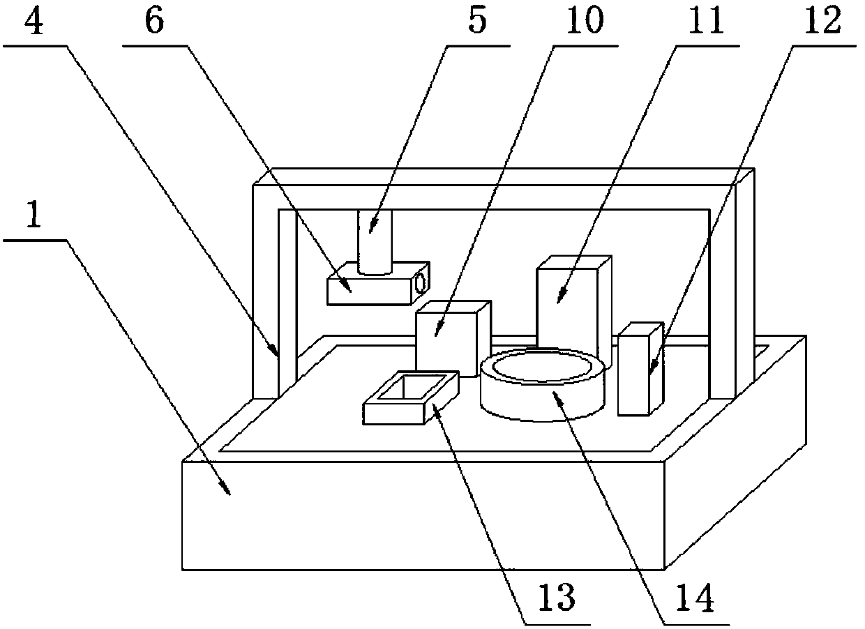
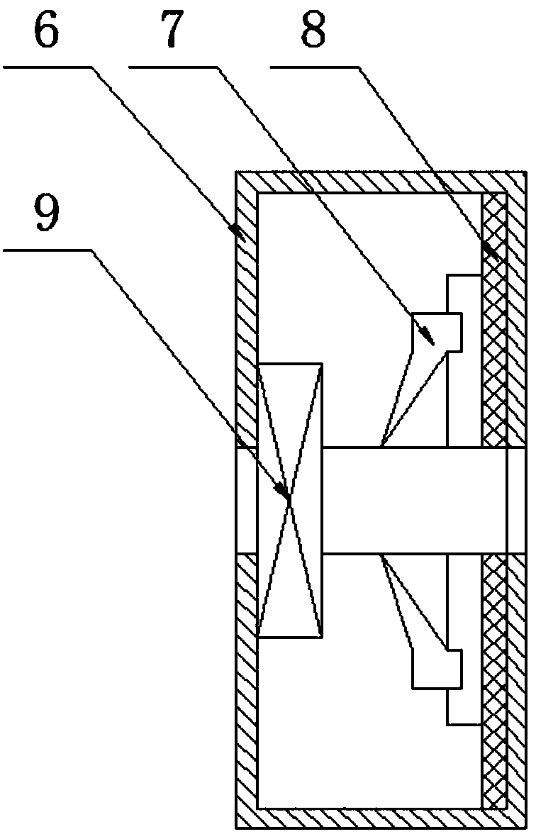
[0017] See Figure 1-4 , The present invention provides a technical solution: a fully automatic wire cutting and tinning machine, including a workbench 1, a control board 2, a chassis 3, a movable frame 4, an electric push rod 5, a splint 6, a peeling tool 7, and a fixed plate 8. , Wire cutting machine 9, soldering flux mechanism 10, tinning mechanism 11, trimming mechanism 12, flux tank 13, tin water tank 14, drive shaft 15, stirring ra...
PUM
Abstract
The invention discloses a fully automatic wire cutting tin dipping machine, which comprises a work table, a control plate, a machine case, a moving frame, an electric push rod, a clamp plate, a peeling cutter, a fixing plate, a cutting machine, a welding flux dripping mechanism, a tin dipping mechanism, a trimming mechanism, a welding flux groove, a tin water groove, a transmission shaft, a stirring frame, a stirring motor, a heating machine, a heat conduction plate, a box door, an external connection plug and moving wheels, wherein the work table is arranged on the top of the machine case through screw bolts; the moving frame is arranged on the top of the work table through screw bolts; the electric push rod is arranged at one side of the moving frame; the clamp plate is arranged at the bottom of the electric push rod through screw bolts; a wire cutting machine is arranged inside the clamp plate through screw bolts; the peeling cutter is correspondingly arranged at one side of the wire cutting machine and is connected with the fixing plate through screw bolts. The tin dipping machine has the advantages that the size is small; the moving is convenient; the wires can be effectivelycut, peeled and dipped with tin; the work efficiency is greatly improved.
Description
Technical field [0001] The invention relates to the technical field of tin dipping machines, in particular to a fully automatic wire cutting tin dipping machine. Background technique [0002] The structure of the wires used in electronic equipment from the outside to the inside is the protective sheath, the insulating sheath and the core wire. In order to make the core wire not loose after stripping, to ensure the welding quality between the wire and the electronic components, and meet a certain high Frequency performance, often dip tin on the end of the wire. In the traditional dip tin process, the usual method is manual operation. Due to the shaking of the hand or the deviation of the line of sight during the manual operation, the wire end cannot be leveled. It is placed in the tin surface of the tin furnace, which results in different depths of tinning at the end of the wire, and it is difficult to guarantee the appearance quality. Problems such as bell mouth, bulge, inconsist...
Claims
Application Information
Patent Timeline
Application Date:The date an application was filed.
Publication Date:The date a patent or application was officially published.
First Publication Date:The earliest publication date of a patent with the same application number.
Issue Date:Publication date of the patent grant document.
PCT Entry Date:The Entry date of PCT National Phase.
Estimated Expiry Date:The statutory expiry date of a patent right according to the Patent Law, and it is the longest term of protection that the patent right can achieve without the termination of the patent right due to other reasons(Term extension factor has been taken into account ).
Invalid Date:Actual expiry date is based on effective date or publication date of legal transaction data of invalid patent.