
Siphon discharge method for metallurgy

A technology of siphoning and metal liquid, applied in the field of metallurgy, can solve the problems of slow liquid discharge process, affecting temperature requirements, slow working efficiency, etc., to achieve the effect of stable liquid flow rate, avoiding cracks and improving efficiency

Active Publication Date: 2019-08-16
GUANGDONG JINYE PRECIOUS METALS CO LTD
View PDF6 Cites 0 Cited by
  • Summary
  • Abstract
  • Description
  • Claims
  • Application Information

AI Technical Summary

Problems solved by technology

[0002] In the metallurgical process of non-ferrous metals, since smelting needs to go through multiple processes, it is necessary to export the molten metal liquid in the smelting furnace and inject it into the next process. The way to release the molten metal liquid is easy to cause metal residue between the valve and the smelting furnace to block the liquid discharge port
Moreover, since the position of the discharge port is fixed, when the liquid level of the molten metal in the smelting furnace is lowered, the flow rate of the liquid discharge port will be correspondingly slowed down, which will cause the work efficiency of the next process to be slow, and eventually lead to the failure of the metallurgical process. Efficiency drops. In addition, due to the slow discharge process, the temperature of the molten metal liquid in the early and late stages of discharge is also different, which also affects the temperature requirements required for the next process.

Method used


Image

  • Siphon discharge method for metallurgy
  • Siphon discharge method for metallurgy

Examples


Embodiment Construction

[0021] The present invention will be further described in detail below in conjunction with the accompanying drawings and specific embodiments.

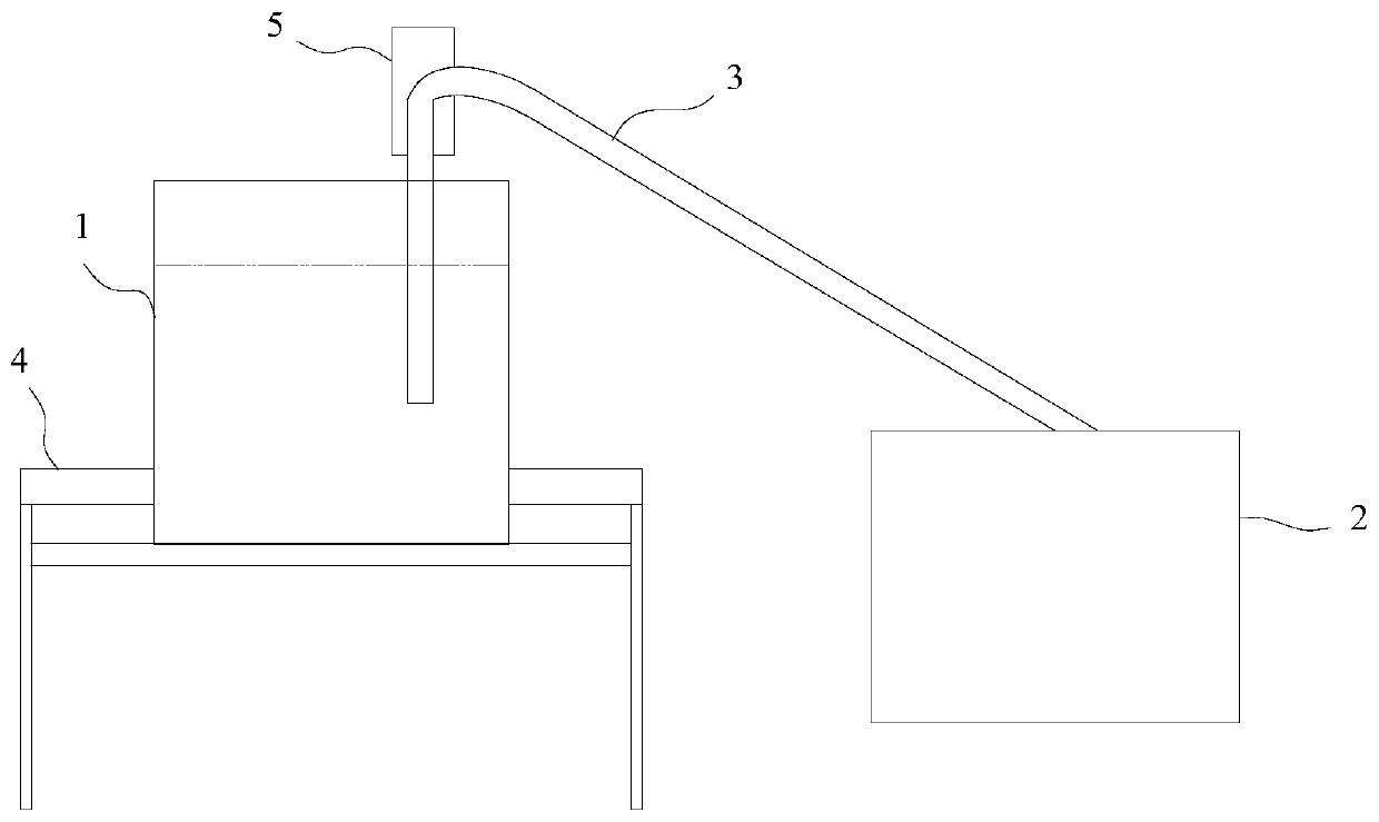
[0022] The method of siphon discharge for metallurgy, such as Figure 1-2 shown, including the following steps:

[0023] One end of the superalloy tube 3 is sealed and slidably inserted into the melting furnace 1, and extended to below the molten metal liquid level of the melting furnace 1, the other end of the superalloy tube 3 is connected to the heat preservation pool 2, and the height of the heat preservation pool 2 is set to be lower than the melting furnace 1 height;

[0024] Use a vacuum pump to vacuumize the superalloy pipe 3 and the heat preservation pool 2 for the first time;

[0025] Preheating the superalloy pipe 3 and the heat preservation pool 2 by means of a heating device;

[0026] The molten metal liquid in the smelting furnace 1 is discharged to the heat preservation pool 2 through the superalloy tube 3 through th...


PUM


Abstract

The invention discloses a siphon liquid discharging method for metallurgy. The siphon liquid discharging method comprises the following steps that one end of a high-temperature alloy pipe is slidablyinserted into a smelting furnace in a sealing manner, the other end of the high-temperature alloy pipe is connected into a heat preservation pool, and the height of the heat preservation pool is set to be less than that of the smelting furnace; the high-temperature alloy pipe and the heat preservation pool are vacuumized by using a vacuum pump for the first time; the vacuumized high-temperature alloy pipe and heat preservation pool are preheated through a heating device; a molten metal liquid in the smelting furnace is discharged from the high-temperature alloy pipe into the heat preservationpool through the siphon effect; the above high-temperature alloy pipe and heat preservation pool are vacuumized by using the vacuum pump for the second time, and the smelting furnace is pressurized byusing a pressurizing air pump in an auxiliary manner; and the height of the smelting furnace is adjusted by using a lifting platform, and / or the flow rate of the molten metal liquid in the high-temperature alloy pipe is adjusted by adjusting the height of the end, extending into the smelting furnace, of the high-temperature alloy pipe through a screw-nut mechanism. By adoption of the siphon liquid discharging method disclosed by the invention, the siphon flow rate of the molten metal liquid can be rapidly and conveniently adjusted to fit the processing speed of the next working procedure.

Description

technical field [0001] The invention relates to the technical field of metallurgy, in particular to a siphon discharge method for metallurgy. Background technique [0002] In the metallurgical process of non-ferrous metals, since smelting needs to go through multiple processes, it is necessary to export the molten metal liquid in the smelting furnace and inject it into the next process. The way to release the molten metal liquid is easy to cause metal residue between the valve and the smelting furnace to block the liquid discharge port. Moreover, since the position of the discharge port is fixed, when the liquid level of the molten metal in the smelting furnace is lowered, the flow rate of the liquid discharge port will be correspondingly slowed down, which will cause the work efficiency of the next process to be slow, and eventually lead to the failure of the metallurgical process. The efficiency drops. In addition, due to the slow discharge process, the temperature of the...

Claims


Application Information

Patent Timeline
Patent Type & Authority Patents(China)
IPC IPC(8): F27D3/14
CPCF27D3/14
Inventor 范才刘德权
Owner GUANGDONG JINYE PRECIOUS METALS CO LTD
Learn More