
Water-hammer arrestor

A technology of eliminator and water hammer, which is applied in the field of pipe fittings manufacturing, can solve problems such as low work efficiency, paralysis of drainage and water supply systems, and strained valve parts, etc., and achieves easy control and use, good water hammer elimination effect, and simple and convenient use Effect

Pending Publication Date: 2018-05-18
QINGHAI XIAOXINIU BIOLOGICAL DAIRY IND
View PDF0 Cites 6 Cited by
  • Summary
  • Abstract
  • Description
  • Claims
  • Application Information

AI Technical Summary

Problems solved by technology

Due to the sudden opening or closing of the valve, the sudden stop of the water pump, the sudden opening and closing of the guide vane, etc., the flow rate changes suddenly, and the pressure fluctuates greatly at the same time, especially when the water flow is cut off or adjusted quickly. In addition, the closed Water hammer can also occur after the valve is suddenly opened or the feedwater pump is started
[0003] Water hammer will cause valve parts to be strained, pipes to be deformed, instruments to be damaged, and cause water pumps to reverse, pipe network pressure to drop, etc. In severe cases, the pipes will rupture and the entire drainage and water supply system will be paralyzed
[0004] Currently commonly used water hammer eliminators include a cylinder and a piston inside the cylinder. This type of water hammer eliminator can eliminate the water hammer effect to a certain extent, but after long-term operation, the gap between the piston and the inner wall of the cylinder The friction force gradually increases due to the influence of scale or other impurities, which affects the normal work of the water hammer
Maintenance is cumbersome and work efficiency is low
There are also water hammer eliminators that use airbags or elastic hose structures. This type of eliminator simply eliminates the impact of water flow through the contraction or expansion of airbags and elastic hoses. Under the impact of water flow, the airbag and elastic hose are easily broken and thus fail, and the service life is short

Method used


Image

  • Water-hammer arrestor

Examples


Embodiment 1

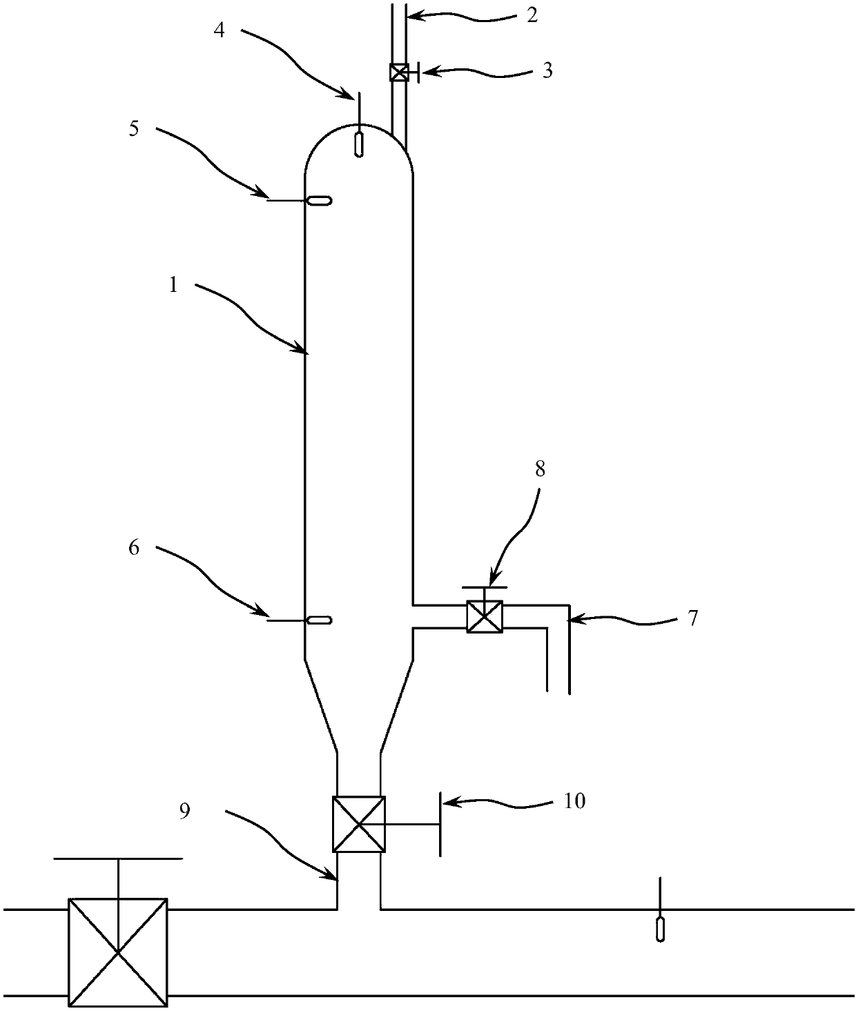
[0049] combine figure 1 As shown, a water hammer eliminator includes a buffer pipe body 1, a compressed air pipeline 2, a pressure sensor 4, a high liquid level sensor 5, a low liquid level sensor 6, a drain pipe 7, and a buffer nozzle 9; The buffer pipe body 1 is a blind pipe with a buffer nozzle 9 at one end, and the closed end of the buffer pipe body 1 is provided with a compressed air pipeline 2 and a pressure sensor 4; the buffer pipe body 1 is provided with a high liquid level sensor 5 near the closed end, and the buffer pipe The body 1 is provided with a low liquid level sensor 6 and a liquid discharge pipe 7 near the end of the buffer nozzle 9 .

[0050]Among them, the compressed air pipeline 2 is provided with a compressed air valve 3; the liquid discharge pipeline 7 is provided with a liquid discharge valve 8; the buffer nozzle 9 is provided with an isolation valve 10. The low liquid level sensor 6 and the discharge pipe 7 are not on the same side, and the distance ...

Embodiment 2

[0053] refer to figure 1 As shown, a water hammer eliminator includes a buffer pipe body 1, a compressed air pipe 2, a pressure sensor 4, a high liquid level sensor 5, a low liquid level sensor 6, a drain pipe 7, a buffer nozzle 9 and a controller; The buffer pipe body 1 is a blind pipe with a buffer nozzle 9 at one end, and the closed end of the buffer pipe body 1 is provided with a compressed air pipeline 2 and a pressure sensor 4; the buffer pipe body 1 is provided with a high liquid level sensor 5 near the closed end, The buffer pipe body 1 is provided with a low liquid level sensor 6 and a liquid discharge pipe 7 at the end close to the buffer pipe mouth 9 .

[0054] Among them, the compressed air pipeline 2 is provided with a compressed air valve 3; the liquid discharge pipeline 7 is provided with a liquid discharge valve 8; the buffer nozzle 9 is provided with an isolation valve 10. The low liquid level sensor 6 and the discharge pipe 7 are not on the same side, and th...

Embodiment 3

[0058] refer to figure 1 Shown, the use of water hammer eliminator, including:

[0059] Close the drain valve 8 and the isolation valve 10, open the compressed air valve 3 and detect the pressure in the buffer pipe body 1, when the pressure in the buffer pipe body 1 is 0.01-0.05MPa lower than the pressure in the fluid pipeline, close the compressed air valve 3, Open the isolation valve 10, and the water hammer arrester starts to work. During water hammer and surge in horizontal pipes, the liquid compresses the volume of the gas inside the bumper rod. The kinetic energy of the liquid is weakened to achieve the purpose of alleviating the water hammer;

[0060] When the liquid level in the buffer tube body 1 reaches the high liquid level sensor 5, close the isolation valve 10, open the liquid discharge valve 8 and the compressed air valve 3, the liquid in the buffer tube body 1 will be discharged through the liquid discharge pipe 7, and the buffer tube body will When the liqui...


PUM


Abstract

The invention relates to the field of pipe fitting manufacturing, in particular to a water-hammer arrestor. The water-hammer arrestor comprises a buffer tube body (1), a compressed air line (2), a pressure sensor (4), a high liquid-level sensor (5), a low liquid-level sensor (6), a drainage pipeline (7), and a buffer tube opening (9); one end of the buffer tube body (1) is provided with a blind tube of the buffer tube opening (9), and the closed end of the buffer tube body (1) is provided with the compressed air line (2) and the pressure sensor (4); and one position, close to the closed end, of the buffer tube body (1) is provided with the high liquid-level sensor (5), and one end, close to the buffer tube opening (9), of the buffer tube body (1) is provided with the low liquid-level sensor (6) and the drainage pipeline (7). Compared with the prior art, the water-hammer arrestor is simple in structure, low in cost, and convenient to use; and the water-hammer arrestor has good removingeffect, no maintenance is required, and the practicability is wide.

Description

technical field [0001] The invention relates to the field of pipe fitting manufacturing, in particular to a water hammer eliminator. Background technique [0002] In water supply systems and liquid flow test devices, it is very frequent to change the fluid path, fluid pressure and fluid flow in the pipeline. Due to the incompressibility of the liquid, the liquid in the pipeline will expand like a solid fixed cylinder, causing water hammer or water hammer. Due to the sudden opening or closing of the valve, the sudden stop of the water pump, the sudden opening and closing of the guide vane, etc., the flow rate changes suddenly, and the pressure fluctuates greatly at the same time, especially when the water flow is cut off or adjusted quickly. In addition, the closed Water hammer can also occur after a valve is suddenly opened or the feedwater pump is started. [0003] Water hammer will cause valve parts to be strained, pipes to be deformed, instruments to be damaged, and cau...

Claims


Application Information

Patent Timeline
Patent Type & Authority Applications(China)
IPC IPC(8): F16L55/052
CPCF16L55/052
Inventor 王维生
Owner QINGHAI XIAOXINIU BIOLOGICAL DAIRY IND
Learn More