
Double-face flange pipeline connection method

A connection method and flange technology, applied in the direction of flange connection, pipe/pipe joint/pipe fitting, through components, etc., can solve the problem of high construction cost of large-diameter pipeline connection, difficult pipeline calibration process, and low pipeline alignment accuracy. problems, to achieve the effect of wide connection applicability, reduced labor intensity, and convenient construction process

Active Publication Date: 2018-05-18
CSSC HUANGPU WENCHONG SHIPBUILDING COMPANY
View PDF5 Cites 4 Cited by
  • Summary
  • Abstract
  • Description
  • Claims
  • Application Information

AI Technical Summary

Problems solved by technology

[0003] In the prior art, connecting equipment pipelines needs to be checked and managed on board, and the process of checking and managing the equipment and pipelines is: checking and managing on the ship → moving back to the workshop for grinding, welding, surface treatment → moving back to the ship for installation, when the diameter of the pipeline to be connected is large When it is very large, the inner diameter of some pipelines can reach more than 300mm, the pipeline is large and heavy, and the space of the ship is narrow, the channel is narrow, and the construction operations of multiple types of work are interspersed, which makes the process of pipeline management very difficult, and The labor intensity of workers is very high, the connection construction cost of large-diameter pipes is high, the operation is difficult, and the alignment accuracy after pipe connection is not high

Method used


Image

  • Double-face flange pipeline connection method
  • Double-face flange pipeline connection method
  • Double-face flange pipeline connection method

Examples


Embodiment Construction

[0034] Below in conjunction with accompanying drawing and embodiment the technical solution of the present invention is further described:

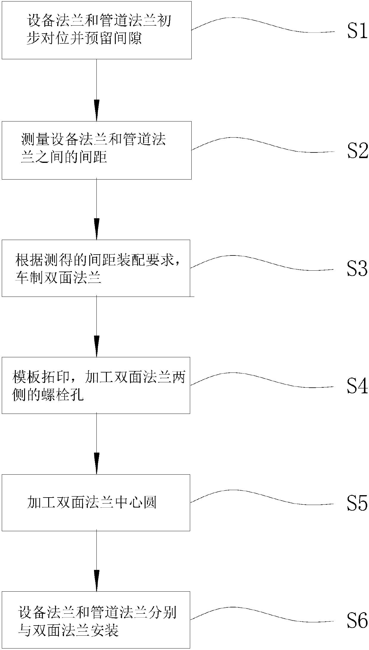
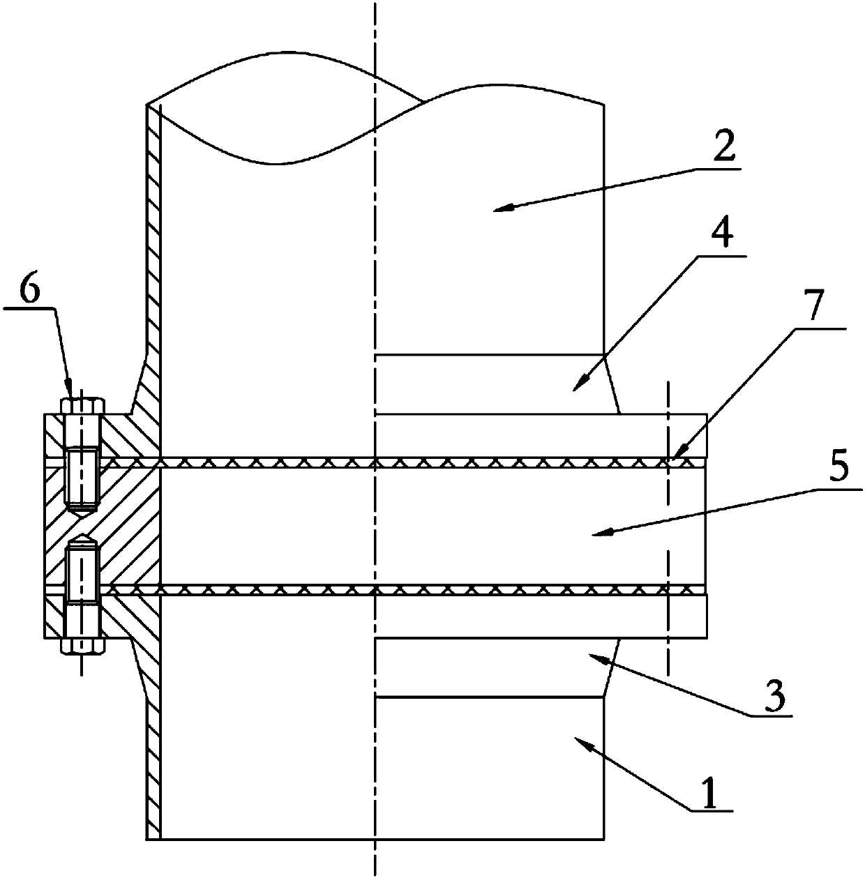
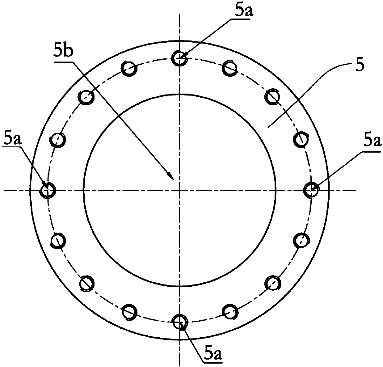
[0035] Such as Figure 1 to Figure 3 As shown, the double-sided flange 5 pipeline connection method in the present embodiment includes the following steps:

[0036] 1) Connect the equipment flange 3 to the equipment nozzle 1, connect the pipeline flange 4 to the pipeline nozzle 2, and perform preliminary alignment on the equipment and the pipeline, so that the center of the equipment flange 3 and the pipeline flange 4 are aligned, and make A gap is reserved between the two. It should be pointed out that after the initial alignment, the connecting end faces of the equipment flange 3 and the pipeline flange 4 are basically kept parallel, and the center of the equipment nozzle 1 is basically aligned with the center of the pipeline. It can simplify the subsequent construction work;

[0037] 2) Measure the distance between multiple quadrant ...


PUM


Abstract

The invention provides a double-face flange pipeline connection method. The double-face flange pipeline connection method comprises the following steps that an equipment flange is connected to an equipment pipe opening; a pipeline flange is connected onto a pipeline pipe opening; equipment and a pipeline are primarily butt jointed, and a clearance is preserved between the equipment and the pipeline; distances between multiple corresponding quadrantal points of the equipment flange and the pipeline flange are measured; a double-face flange is turned according to the measured distances and assembly requirement of the equipment flange and the pipeline flange; templates are used for rubbing, and bolt holes of the double-face flange are machined according to the templates; a central circle of the double-face flange is machined according to the inner diameter of the equipment and the inner diameter of the pipeline; the double-face flange is placed between the pipeline flange and the equipment flange and are aligned; and bolts on two sides of the double-face flange are arranged. By adopting the double-face flange pipeline connection method with the technical scheme, the double-face flangepipeline connection method is simple in construction; labor intensity of workers can be lowered; construction cost is low; connection between the equipment and the pipeline is stable; and pipeline aligning precision is high.

Description

technical field [0001] The invention relates to the technical field of pipeline connection, in particular to a double-sided flange pipeline connection method. Background technique [0002] Modern ships are manufactured by carrying and splicing modules on the berth in the form of sections or general sections. Usually, pipelines are outfitted in sections, equipment is installed on the general section or on the berth, and the equipment and pipelines are completed after the hull is closed. Connection: Due to the strict requirements on the alignment, there are strict requirements on the centering of the equipment nozzle flange connection. The equipment nozzle and the pipe flange cannot be forcibly aligned to avoid external forces on the equipment flange. [0003] In the prior art, connecting equipment pipelines needs to be checked and managed on board, and the process of checking and managing the equipment and pipelines is as follows: checking and managing on the ship → moving ba...

Claims


Application Information

Patent Timeline
Patent Type & Authority Applications(China)
IPC IPC(8): F16L23/024F16L23/18
CPCF16L23/024F16L23/18
Inventor 梁永康徐进初杨山林
Owner CSSC HUANGPU WENCHONG SHIPBUILDING COMPANY
Learn More