
Six-pole mixed magnetic bearing

A hybrid magnetic bearing and axial technology, applied in the field of machinery and electrical transmission, can solve the problems of reduced magnetic bearing performance, low degree of freedom coupling, large drive circuit size, etc., to reduce manufacturing and operating costs, and reduce the number of switch tubes , the effect of saving radial space

Inactive Publication Date: 2018-05-18
JIANGSU UNIV
View PDF10 Cites 7 Cited by
  • Summary
  • Abstract
  • Description
  • Claims
  • Application Information

AI Technical Summary

Problems solved by technology

At present, most magnetic bearings adopt a four-pole or eight-pole structure, driven by 2-way bipolar switching power amplifier or 4-way unipolar switching power amplifier, the driving circuit is bulky, the control is complicated, and the cost is high
[0003] Chinese patent application number CN200820215847.1 discloses a radial two-degree-of-freedom outer rotor hybrid magnetic bearing structure, the radial stator is a symmetrically arranged eight-pole structure, and a two-piece eight-pole structure is used to control the radial two There are four degrees of freedom, so four unipolar (or bipolar) DC power amplifier circuits are required for drive control. This octapole structure has a low coupling degree of two radial degrees of freedom, a large bearing capacity, and a large weight and volume. , the cost is too high, which limits its development and promotion
The "three-degree-of-freedom AC-DC radial-axial hybrid magnetic bearing and its control method" disclosed in the Chinese patent application number CN200510040066.4 adopts a three-phase inverter-driven three-pole magnetic bearing, which greatly reduces the The size of the power amplifier and the cost of the magnetic bearing, but the problems of this magnetic bearing are: the spatial asymmetry of the three-pole structure and the condition that the sum of the three-phase currents of the three-phase inverter is zero, so that the radial levitation force is The maximum levitation force in the direction of the magnetic pole and the opposite direction of the magnetic pole are different. When designing the magnetic bearing, the direction of the minimum levitation force must meet the bearing capacity requirements, which will inevitably lead to an increase in the volume of the magnetic bearing; The nonlinearity between levitation force, current and displacement also enhances the coupling between the two radial degrees of freedom and reduces the performance of the magnetic bearing; in addition, the axial degree of freedom of the bearing is controlled by a DC power amplifier, increasing the Magnetic bearing volume and cost
Chinese patent application number CN201610971589.9 discloses a two-degree-of-freedom permanent magnet bias radial hybrid magnetic bearing, which adopts a radial twelve-stage structure and is embedded in six non-adjacent stator poles. There are permanent magnets, and the remaining 6 magnetic poles are wound around the control coil to form a three-phase star structure. The bearing has a compact structure, a large bearing capacity, and a low coupling degree of the two radial degrees of freedom, but there is a problem: the number of radial magnetic poles Too much, the space reserved for the control coil is small and not conducive to heat dissipation; in addition, due to the existence of 6 non-controllable magnetic poles, the negative displacement stiffness is large, once the rotor is eccentric, it is difficult to return to the equilibrium position, and when rotating at high speed, the The core loss of the magnetic bearing is large

Method used


Image

  • Six-pole mixed magnetic bearing
  • Six-pole mixed magnetic bearing
  • Six-pole mixed magnetic bearing

Examples


Embodiment Construction

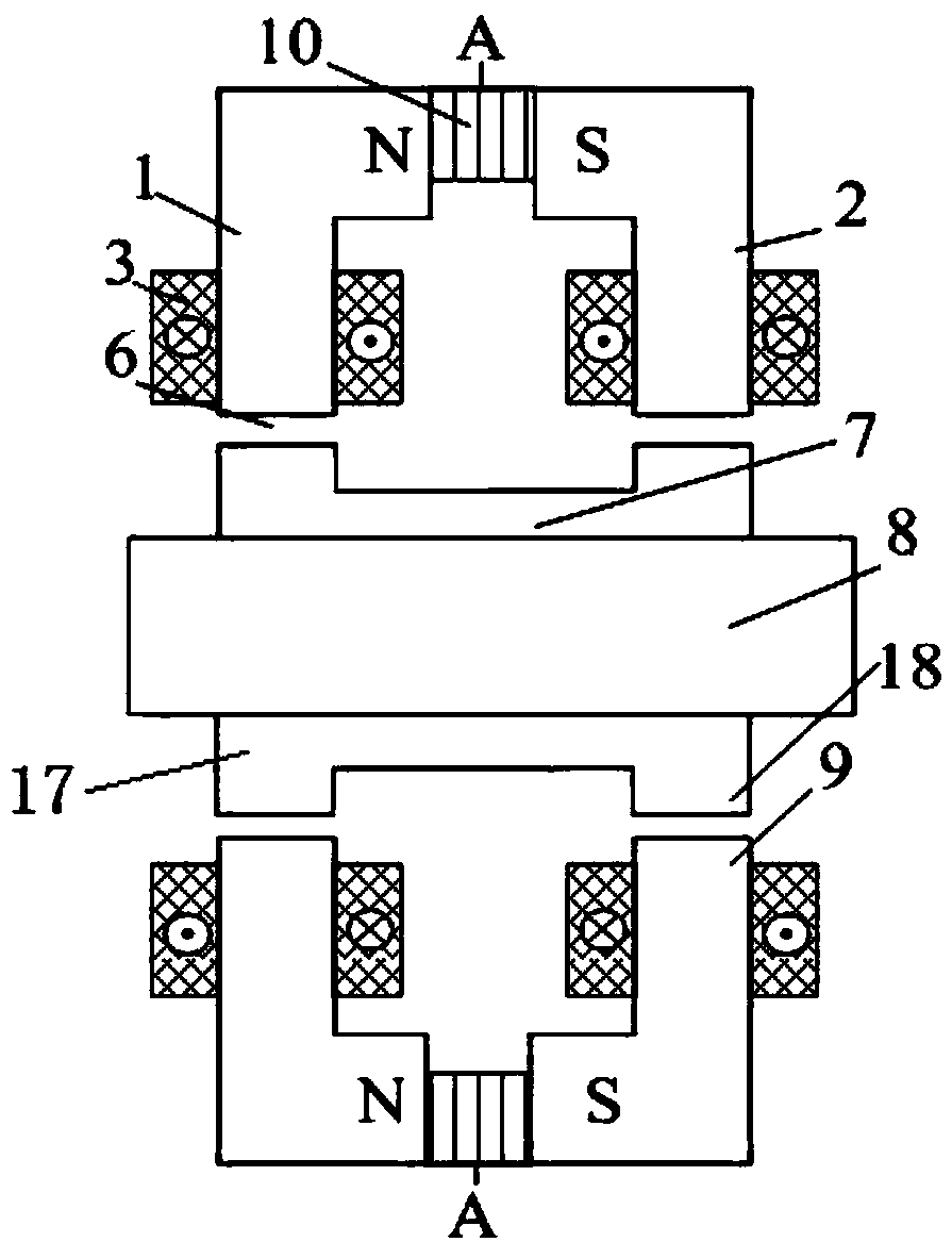
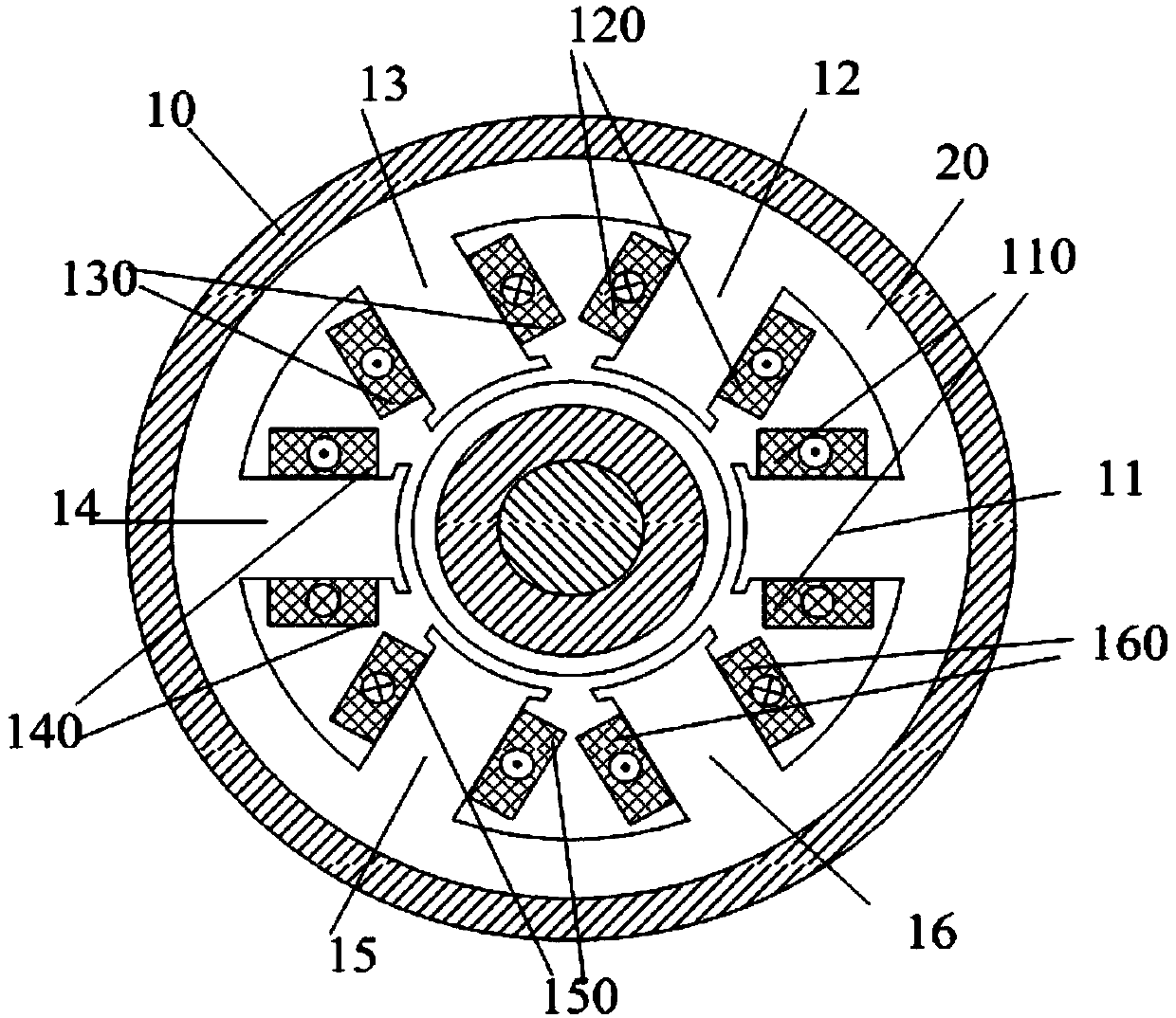
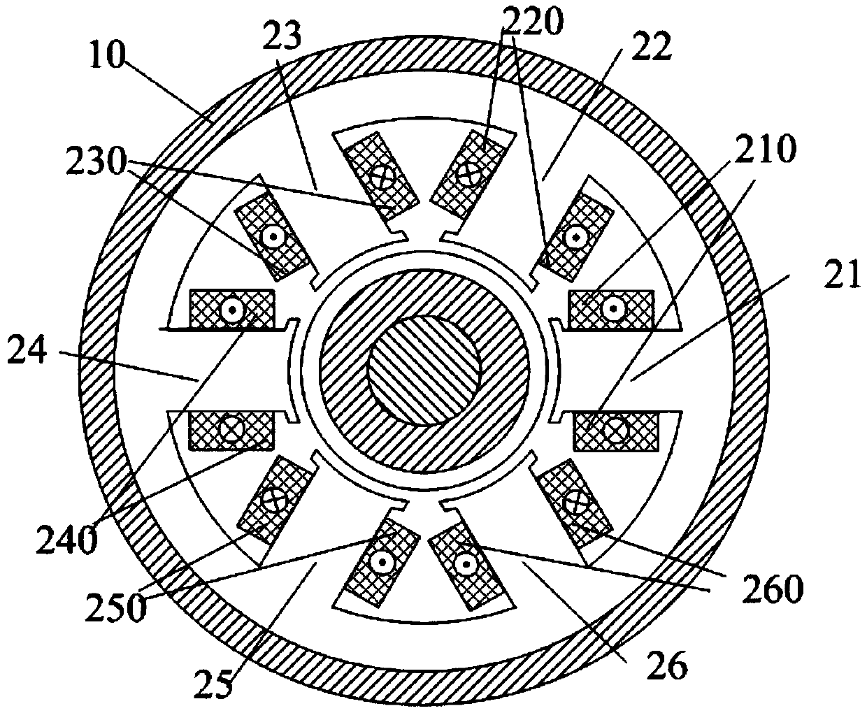
[0020] Such as figure 1 As shown, the present invention is made up of rotating shaft 8, rotor 7, permanent magnet 10, left stator core 1, right stator core 2 and control coil 3. The center of the present invention is the rotating shaft 8, the outer coaxial fixed sleeve of the rotating shaft 8 has the rotor 7, the outer coaxial sleeve of the rotor 7 has the left stator core 1 and the right stator core 2, and the structure of the left stator core 1 and the right stator core 2 is the same, but Arranged symmetrically on the left and right in the axial direction. The left end and the right end of the rotor 7 are respectively provided with a force plate, which are respectively the left force plate 17 and the right force plate 18. The two force plates are coaxial with the rotor 7 and have the same structure. The outer diameters of the two force plates are Larger than the outer diameter of the rotor 7, the two stressed disks can be integrated with the rotor 7. The same radial air ga...


PUM


Abstract

The invention discloses a six-pole mixed magnetic bearing. The rotors are coaxially sleeved with left stator iron cores and right stator iron cores which are symmetrically arranged in the axial direction, left stress discs are arranged at the left ends of the rotors, and right stress discs are arranged at the right ends of the rotors, and circular ring-shaped permanent magnets are laminated between yoke portions of the left stator iron cores and the right stator iron cores; the permanent magnets are axially magnetized, six stator magnetic poles are uniformly distributed in each of the left stator iron cores and the right stator iron cores in the circumferential direction, the six stator magnetic poles of each left stator iron core are aligned with the corresponding left stress disc in theradial direction, and the six stator magnetic poles of each right stator iron core are aligned with the corresponding right stress disc in the radial direction; and the two radial control coils whichare in face-to-face and radial direction on the same stator iron core in the left stator iron core and the right stator iron core are connected in series with a same winding direction, and the two radial control coils which are in axial-facing direction on the left stator iron core and the right stator iron core are connected in series with an opposite winding direction. According to the six-polemixed magnetic bearing, suspension force and displacement characteristics and suspension force and current characteristics tend to be linear, and coupling between two radial degrees of freedom is reduced.

Description

technical field [0001] The invention relates to a non-contact magnetic suspension bearing, referred to as a magnetic bearing, which is a hybrid magnetic bearing that can control two degrees of freedom in the radial direction and an axial degree of freedom, and is suitable for aerospace, nuclear energy, wind power generation, biomedicine, flywheel storage Energy, high-speed electric spindles and the support of various rotating machinery in other industrial fields belong to the field of mechanical and electrical transmission. Background technique [0002] Magnetic bearings use electromagnetic force to suspend the rotor in the air, so that there is no mechanical contact between the rotor and the stator. Magnetic bearings can be divided into single-degree-of-freedom magnetic bearings (axial magnetic bearings), two-degree-of-freedom magnetic bearings (radial magnetic bearings) and three-degree-of-freedom magnetic bearings (radial-axial magnetic bearings) according to the number o...

Claims


Application Information

Patent Timeline
Patent Type & Authority Applications(China)
IPC IPC(8): F16C32/04
CPCF16C32/0451F16C32/0465F16C32/0485
Inventor 朱熀秋龙勇吴熙
Owner JIANGSU UNIV
Learn More