


Quick Research
Generate reliable direction feasibility study reports for your R&D in just a few steps.

Technical Q&A
Discover and master advanced knowledge NOW. Basics, ideas, possibilities, all at once.

Find Solutions
As an expert in R&D theories, this can generate solutions to your technical problems instantly.

Evaluate Feasibility
Analyze your overall solution with one click, know your potential R&D risks in advance.

Monitor Landscape
Get weekly tech updates, stay abreast of the latest tech innovations and key insights.
Thermal-stamping formation method for rapidly and efficiently realizing performance gradient distribution of high-strength steel part
A technology of hot stamping and gradient distribution, which is applied to forming tools, vehicle parts, manufacturing tools, etc., to achieve the effects of avoiding heat consumption, reducing heating energy, and saving time
- Summary
- Abstract
- Description
- Claims
- Application Information
AI Technical Summary
Problems solved by technology
Method used
Image

Examples
Embodiment 1
[0079] Partition cooling hot stamping forming method
[0080] Such as Figure 22 As shown, the zoned cooling method is used to realize the situation that the front region (A region) of the thermoformed part is a martensitic phase, and the rear region (B region) is a mixed phase of ferrite and pearlite. A high-strength steel sheet 600 with a size of 1200mm×600mm×1.5mm and a material of 22MnB5 is used as the operation object, and is divided into two areas in the length direction.
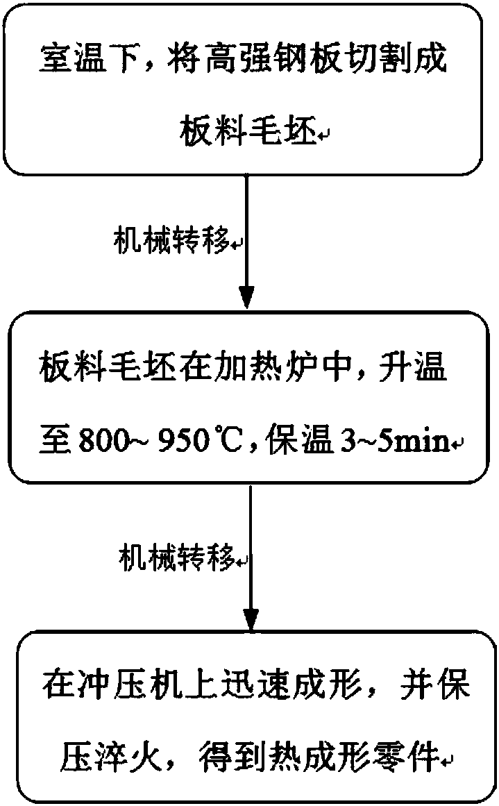
[0081] Proceed as follows:
[0082] 1. Use a cutting machine to cut a piece of high-strength steel sheet 600 with a size of 1200mm×600mm×1.5mm and a material of 22MnB5.
[0083] 2. The control system in the upper mold base 100 controls the upper mold mechanism to drive the upper fixed plate 120 and the upper six mold blocks (front mold blocks 510a, 510b, 510c, rear mold blocks 520a, 520b, 520c) to The front moves to the maximum position at a speed of 0.2m / s and stops.
[0084] 3. Place and positio...
Embodiment 2
[0092] Partition heating hot stamping forming method
[0093] like Figure 22 As shown, the front region (A region) of the thermoformed part is a martensitic phase, and the rear region (B region) is a mixed phase of ferrite and pearlite by using a zoned heating method. A high-strength steel sheet 600 with a size of 1200mm×600mm×1.5mm and a material of 22MnB5 is used as the operation object, and is divided into two areas in the length direction.
[0094] Proceed as follows:
[0095] 1. Use a cutting machine to cut a piece of high-strength steel sheet 600 with a size of 1200mm×600mm×1.5mm and a material of 22MnB5.
[0096] 2. The internal control system of the upper mold base 1 controls the upper mold mechanism to drive the upper fixed plate 120 and the upper six mold blocks (the front mold blocks 510a, 510b, 510c, and the rear mold blocks 520a, 520b, 520c) to The front moves to the maximum position at a speed of 0.2m / s and stops.
[0097] 3. Place and position the cut high-...
PUM
| Property | Measurement | Unit |
|---|---|---|
| yield strength | aaaaa | aaaaa |
Abstract
Description
Claims
Application Information
 - R&D Engineer
- R&D Manager
- IP Professional
- Industry Leading Data Capabilities
- Powerful AI technology
- Patent DNA Extraction
Browse by: Latest US Patents, China's latest patents, Technical Efficacy Thesaurus, Application Domain, Technology Topic, Popular Technical Reports.
© 2024 PatSnap. All rights reserved.Legal|Privacy policy|Modern Slavery Act Transparency Statement|Sitemap|About US| Contact US: help@patsnap.com