
Spinning winding roller machining technology

A processing technology and winding roller technology, which is applied in the field of spinning and winding roller processing technology, can solve the problems of poor coaxiality, easy deformation, and large jumping of the spinning and winding roller, so as to improve product quality and reduce the amount of deformation. , the effect of twisting quality improvement

Active Publication Date: 2018-05-15
杭州量创科技咨询有限公司
View PDF5 Cites 0 Cited by
  • Summary
  • Abstract
  • Description
  • Claims
  • Application Information

AI Technical Summary

Problems solved by technology

[0003] The purpose of the present invention is to overcome the problems of large runout, poor coaxiality and easy deformation of existing spinning winding rollers processed by turning, and to provide a spinning winding roller with small runout, good coaxiality and not easily deformed. Roll processing method

Method used


Image

  • Spinning winding roller machining technology
  • Spinning winding roller machining technology

Examples


Embodiment Construction

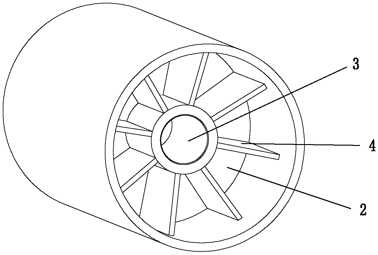
[0020] Such as Figure 1-Figure 2 As shown, one end of the spinning winding roller is provided with a concave first cylindrical hole 1, and the other end is provided with a concave second cylindrical hole 2, and there is a section between the first cylindrical hole 1 and the second cylindrical hole 2. The first cylindrical hole and the second cylindrical hole and its diameter is smaller than the through hole 3 of the diameter of the first cylindrical hole and the second cylindrical hole, and the inside of the second cylindrical hole is provided with supporting ribs distributed along the circumference of the second cylindrical hole wall 4. The through hole extends toward the second cylindrical hole to the middle of the second cylindrical hole, and the wall of the through hole formed in the second cylindrical hole is fixedly connected with the supporting rib 4 .

[0021] The spinning winding roll includes the following processing steps: the first step is to use nylon and glass fi...


PUM


Abstract

The invention provides a spinning winding roller machining technology and belongs to the technical field of spinning equipment parts. The technology comprises the following machining steps that nylonand glass fiber are adopted as raw materials, and are molded in an injection manner through an injection molding machine at the temperature of 245-255 DEG C; a spinning winding roller blank molded inan injection manner is placed for one to two months at the normal temperature; the blank obtained after normal temperature aging treatment is placed into clear water with the temperature between 15 DEG C and 25 DEG C to be subjected to aging treatment in water again, placing time is between 4.5 hours and 5 hours, and elastic deformation of the blank is further reduced; inner hole turning is carried out on the blank obtained after aging treatment in the water, and in the turning process, a first cylinder hole and a through hole are turned and formed at the same time; a tungsten steel reamer isadopted for grinding and penetrating the through hole; the bank formed through primary turning is placed into the water to be treated at the constant temperature; the blank which is placed in the water and machined primarily is taken out, the grinded inner hole serves as a locating basis, double-tip clamping and locating are adopted, and turning of the outer circle periphery face is carried out; and a circumferential rolling depression wheel is adopted for carrying out surface finishing process to form the product.

Description

technical field [0001] The invention belongs to the technical field of textile equipment components, and in particular relates to a spinning winding roller processing technology. Background technique [0002] Spinning winding roll is one of the important components commonly used in textile equipment, mainly used to frictionally drive the cross-winding bobbin rotating in the winding frame installed on the winding device. Such as Figure 1-Figure 2 As shown, one end of the spinning winding roller is provided with a concave first cylindrical hole 1, and the other end is provided with a concave second cylindrical hole 2, and there is a section between the first cylindrical hole 1 and the second cylindrical hole 2. The first cylindrical hole and the second cylindrical hole and its diameter is smaller than the through hole 3 of the diameter of the first cylindrical hole and the second cylindrical hole, and the inside of the second cylindrical hole is provided with supporting ribs ...

Claims


Application Information

Patent Timeline
Patent Type & Authority Applications(China)
IPC IPC(8): B29C69/00
CPCB29C69/00B29C69/001
Inventor 陈银顾丽敏田美霞
Owner 杭州量创科技咨询有限公司
Learn More